
Data Recording Apparatus

a technology for recording apparatuses and data, applied in the field of data recording apparatuses, can solve the problems of easy error, difficult tracking of such changes over a long period of time, in particular over the entire lifetime, and no longer being able to provide manufacturers with the view of the installation location and associated configurations of intelligent electronic devices to be monitored

Inactive Publication Date: 2009-07-16
ABB RES LTD
View PDF37 Cites 4 Cited by
  • Summary
  • Abstract
  • Description
  • Claims
  • Application Information

AI Technical Summary

Benefits of technology

[0009]Knowledge of the current status or the current configuration with regard to production and product data of a specific installation of an intelligent electronic device (IED) for monitoring and / or driving a primary device appertaining to medium- and high-voltage technology is therefore useful for the monitoring and / or the maintenance of the intelligent electronic device after it has been produced and sold. Particularly for the manufacturer of the intelligent electronic device, whose aid is requested in the event of a disturbance or a fault in the intelligent electronic device, it is useful to know where a corresponding intelligent electronic device is located and how this intelligent electronic device is configured, in order that the manufacturer can directly initiate the necessary actions for rectifying the disturbance or the fault without inspecting the intelligent electronic device beforehand.
[0012]Furthermore a data recording apparatus is disclosed for recording production and product data output from at least one intelligent electronic device, which data recording apparatus enables continuous tracking of a configuration and detection of installed components of the intelligent electronic device.

Problems solved by technology

In an inexpedient manner, it is furthermore possible that the installed intelligent electronic devices change their installation location in such a way that an overview of the installation locations and associated configurations of the intelligent electronic devices to be monitored is no longer possible for the manufacturer.
When intelligent electronic devices are installed in industrial environments, in particular in medium-voltage switching stations and high-voltage switching stations, there is the problem that changes in requirements, fitted parts and configurations take place continuously in part, with the result that tracking such changes over a long period of time, in particular over the entire lifetime, is very difficult and prone to error.

Method used


Image

  • Data Recording Apparatus
  • Data Recording Apparatus
  • Data Recording Apparatus

Examples


Embodiment Construction

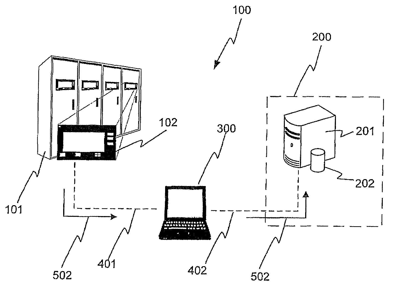
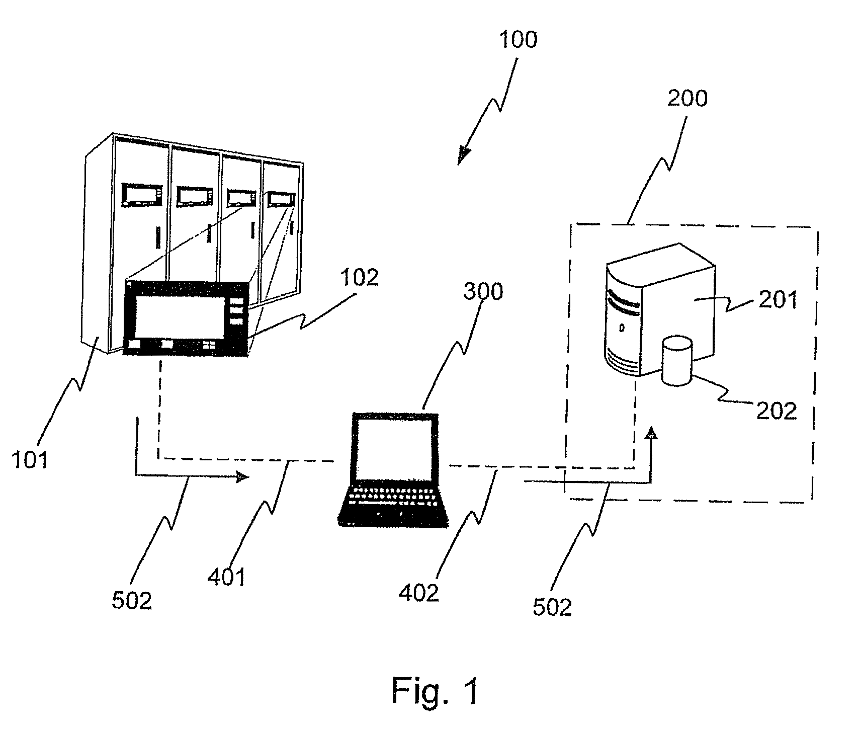
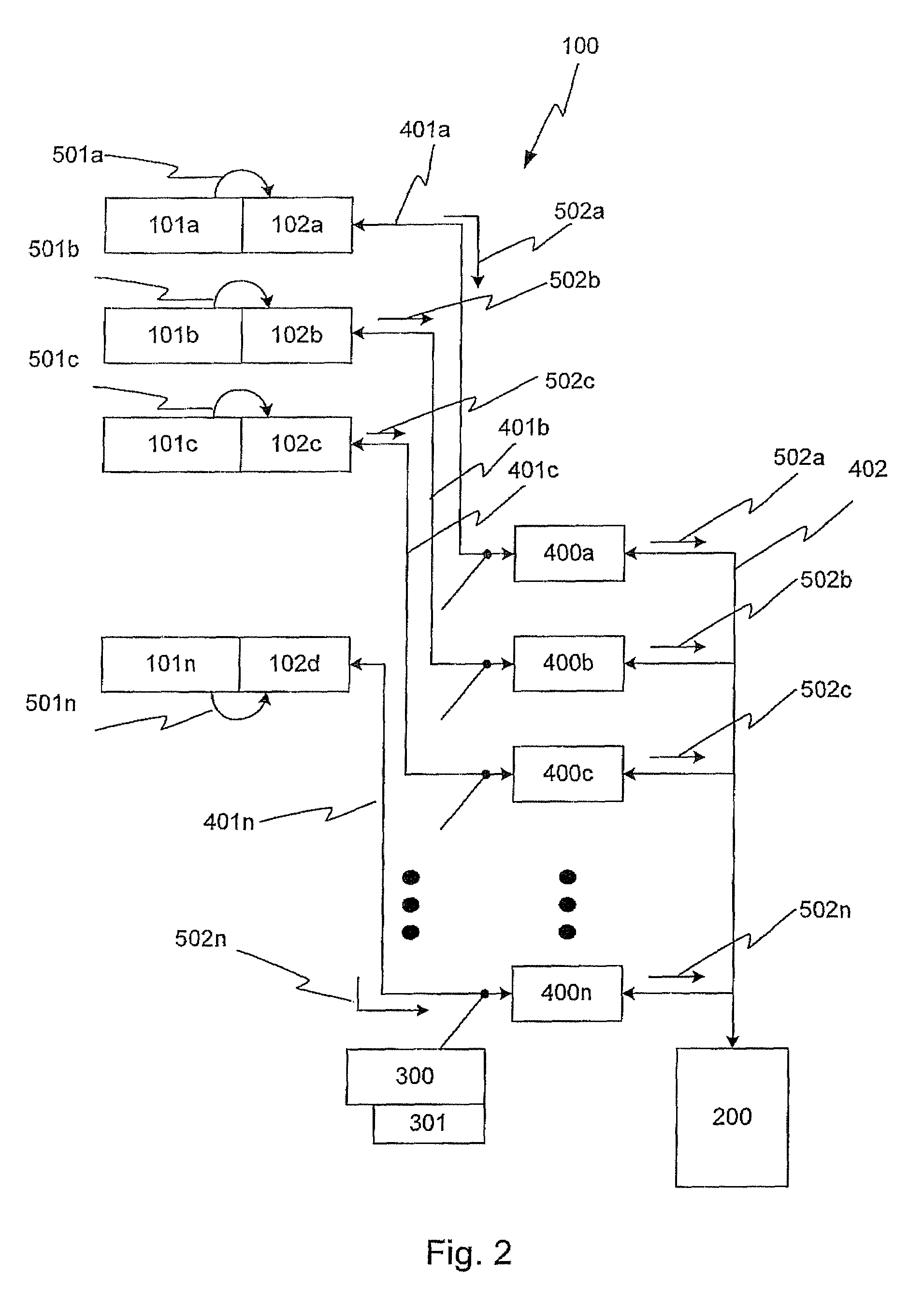
[0030]One aspect of the disclosure consists in providing, by means of a configuration device connected between a data collector device assigned to the at least one intelligent electronic device to be monitored and the storage device, an efficient control of the storage of the production and product data provided by the collector device, said data being transmitted as transmission data from the intelligent electronic device to be monitored to the storage device. The transmission data comprise, in particular, the production and product data of the intelligent electronic device (IED).

[0031]In this case, the transmission data are firstly transmitted from the collector device to the configuration device via a first data transmission path. These transmission data transmitted to the configuration device are then transmitted from the configuration device to the storage device via a second data transmission path. This firstly makes it possible that the first data transmission path and the se...


PUM


Abstract

A data recording apparatus is disclosed for recording production and product data output from at least one electronic device. A data collector device assigned to the electronic device records the production and product data and converts said data into transmission data to be transmitted, which are subsequently stored in a storage device. A configuration device connected between the data collector device and the storage device controls the storage of the transmission data.

Description

RELATED APPLICATION[0001]This application claims priority as a continuation application under 35 U.S.C. §120 to PCT / EP2007 / 056963 filed as an International Application on Jul. 9, 2007 designating the U.S., the entire content of which is hereby incorporated by reference in its entirety.TECHNICAL FIELD[0002]The present disclosure relates generally to a method for transmitting production and product data of an intelligent electronic device to a remote storage device or a remote storage system. The present disclosure also relates to a data recording apparatus.BACKGROUND INFORMATION[0003]Electrical devices—also referred to as primary devices—appertaining to medium- and high-voltage technology such as, for example, power transformers, converter stations, line devices, power circuit-breakers, isolating switches, grounding switches, busbars, motors, generators, etc., after production and sale to the end user, are usually present at different locations and have to be monitored there and prot...

Claims


Application Information

Patent Timeline
IPC IPC(8): G06F13/00
CPCG05B19/042G05B2219/23414G05B2219/24041G05B2219/25205G05B2219/25061G05B2219/25109G05B2219/24168
Inventor DECK, BERNHARDGULLI, LORENZOVOGT, WERNER
Owner ABB RES LTD
Learn More