
Control loop and method of creating a process model therefor

Inactive Publication Date: 2009-07-16
POWITEC INTELLIGENT TECHNOLOGIES GMBH
View PDF10 Cites 12 Cited by
  • Summary
  • Abstract
  • Description
  • Claims
  • Application Information

AI Technical Summary

Benefits of technology

[0007]Because the process model provides specialized function approximators for various process dynamics, and the specialized function approximators then have to be selected, it is possible to better approach the individual phases of the process with better predictions. The method employed by an exemplary embodiment of this disclosure is to model the process dynamics with adaptive, learning-capable and self-organizing function approximators, for example by using neural netw

Problems solved by technology

As a result, there is a risk that significant channels are not considered and also that computing power is consumed for non-significant channels.

Method used


Image

  • Control loop and method of creating a process model therefor
  • Control loop and method of creating a process model therefor
  • Control loop and method of creating a process model therefor

Examples


Embodiment Construction

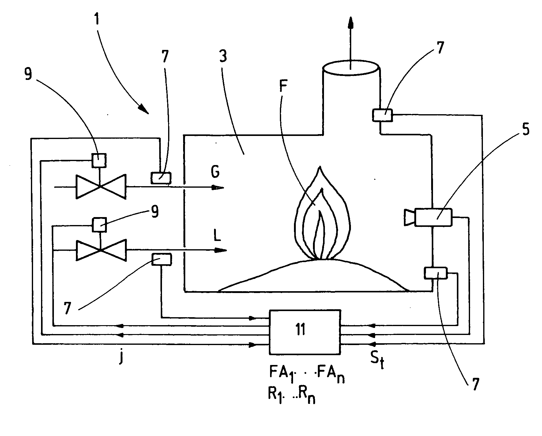
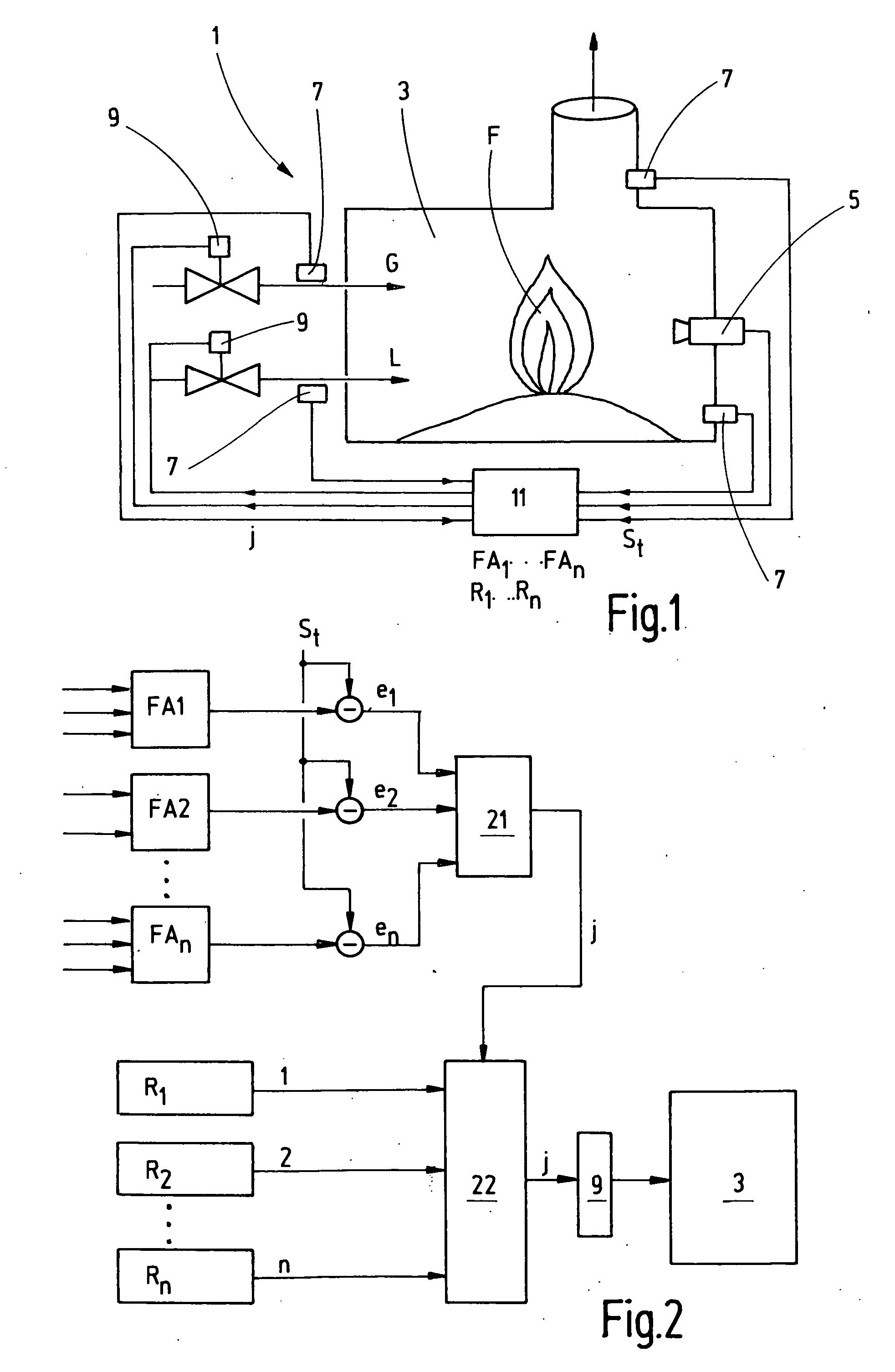
[0016]A plant 1, for example a coal-fired, oil-fired or gas-fired power station, a waste incineration plant or a cement works (i.e., a plant for making cement), comprises a furnace 3 (which should also be understood to mean a grate or other suitable device for use in facilitating the below-discussed combustion), at least one observation device 5 that can image the interior of the furnace 3 (or the grate), preferably further sensors 7, at least one adjustment device 9, and a computer 11 to which the observation device(s) 5, further sensors 7 and adjustment device(s) 9 are connected.

[0017]The furnace 3 is supplied with fuel or some other material to be converted, referred to as G for short, for example coal, oil, gas, waste, lime or similar, as well as with primary air (or primary oxygen) and secondary air (or secondary oxygen), referred to as L for short, and this supply is regulated by the adjustment devices 9 that are controlled by the computer 11. A combustion process takes place ...


PUM


Abstract

In a control loop for regulating a combustion process in a plant having a controlled system for converting material by way of the combustion, with at least one flame body being formed, the control loop having at least one observation device for imaging the flame body and further sensors to determine the state variables describing the state of the system in the plant, at least one regulator and / or a computer to evaluate the state variables and select suitable actions based on a process model, and adjustment devices for at least the supply of material and / or air that can be controlled by the actions, the process model provides specialized function approximators for various process dynamics, one of which function approximators is selected by a selector, and a regulator assigned to the selected function approximator is used to regulate the control loop.

Description

CROSS-REFERENCE TO RELATED APPLICATION[0001]The present application claims priority to EP 08 000 618.2, which was filed Jan. 15, 2008. The entire disclosure of EP 08 000 618.2 is incorporated herein by reference.TECHNICAL FIELD[0002]The present disclosure generally relates to a control loop for regulating a combustion process in a plant (e.g., a power-generating plant, a waste incineration plant or a plant for making cement) having a controlled system for converting material by way of the combustion process, with at least one flame body being formed, and the control loop having at least one observation device for imaging the flame body, further sensors for determining the state variables that describe the state of the system in the plant, and a controller for evaluating the state variables and selecting suitable actions based on a process model, and adjustment devices that can be controlled by the actions for at least the supply of the material and / or air.BACKGROUND[0003]In a known ...

Claims


Application Information

Patent Timeline
IPC IPC(8): G05B13/04G06F15/18
CPCF23N5/00F23N2023/42F23N2023/40F23N2223/40F23N2223/42G05B19/418
Inventor WINTRICH, FRANZSTEPHAN, VOLKER
Owner POWITEC INTELLIGENT TECHNOLOGIES GMBH
Learn More