
Head mounted display

a display and head technology, applied in the field of head mounted displays, can solve the problems of frame being brought into contact with the display section, inability to obtain accurate display images, and increased display section size, so as to eliminate the possibility of misalignment, clear image, and the effect of improving accuracy

Inactive Publication Date: 2009-07-16
KONICA MINOLTA INC
View PDF3 Cites 131 Cited by
  • Summary
  • Abstract
  • Description
  • Claims
  • Application Information

AI Technical Summary

Benefits of technology

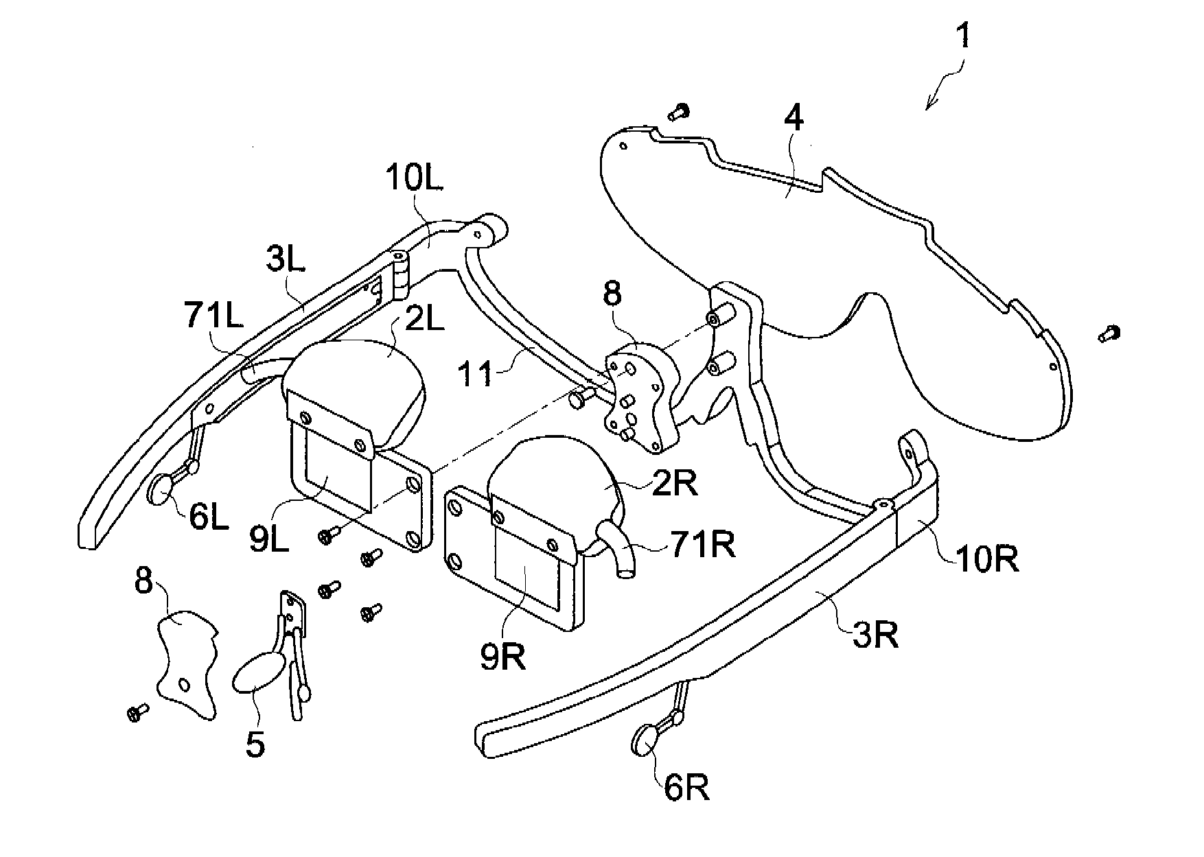
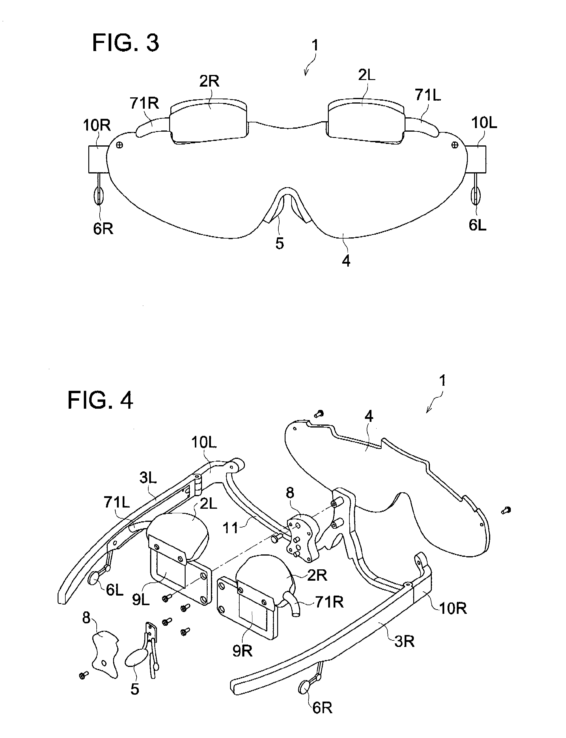
[0057]According to the invention described in claim 1, the eyepiece optical system is supported at the center position in the lateral direction of the face of the user. This arrangement ensures that the eyepiece optical system is not affected by possible deformation of the front frame section due to the size of the face or head of the user. This eliminates the possibility of misalignment caused between the position of the user's eyes and the direction of the image led by the eyepiece optical system, and provides the user with a clear image. Further, the eyepiece optical system is supported at the center. This arrangement prevents the external light from being interrupted and allows the user to view the external world over an extensive range.
[0058]According to the invention described in claims 2 through 4, the transparent plate covering the eyepiece optical system is provided. This makes it possible for the display to look like commonly used eyeglasses or sunglasses.
[0059]According to the invention described in claim 5, the eyepiece optical system is each located right and left so that the video can be observed by both eyes, with the result that the displayed image and information can be viewed with higher accuracy.
[0060]According to the invention described in claim 6, the transparent plate is detachably mounted so that the transparent plate and optical element can be cleaned. Further, it is possible to select and mount the transparent plate conforming to the brightness of the operation environment and user's taste. This enhances the degree of freedom for the user.
[0061]According to the invention described in claim 7, the optical pupil led by the eyepiece optical system is larger than the user's pupil. This arrangement allows the user to view the image more reliably.
[0062]According to the invention described in claim 8, the user can view the image light superimposed on the external light. This allows the user to observe the external world while obtaining information from the image light.

Problems solved by technology

In conventional image display devices, the display section connected to the frame is displaced by the bending of the frame, and the video on the display section is disturbed, with the result that accurate view of the displayed image cannot be obtained.
Further, to prevent bending of the display section the display section is designed in a rigid structure, and this has increased size of the display section.
However, there is a problem that the frame is brought in contact with the display section due to the bending of the frame.
However, since the display section is located outside, the appearance of this display is not similar to that of the commonly used eyeglasses or sunglasses.
In this sense, the appearance of this display has not been favorably accepted.

Method used


Image

  • Head mounted display
  • Head mounted display
  • Head mounted display

Examples


modified example 1

[0137]FIG. 7 shows the HMD 1 as a modified example 1. The same portions will be assigned with the same reference numerals, and the description will be omitted to avoid duplication.

[0138]The HMD 1 as the modified example 1 is so designed that it can be used even by a user of poor vision. When the user has a poor vision, the vision must be corrected. For example, the dark transparent plate 4 is replaced by the transparent plate conforming to the vision of the user. However, according to this method, the bright external world can be observed when the dark transparent plate 4 is replaced, but there occurs a problem that the image led from the prisms 9R and 9L is viewed by the naked eyes and is difficult to view clearly. In the HMD 1 of the modified example 1, a dioptric lens conforming to the vision of the user is mounted between the user's eyes and prisms 9R and 9L so that the user's vision is corrected to allow the user to view a clean image at all times.

[0139]As illustrated, the diop...

modified example 2

[0141]FIG. 8 shows the HMD 1 as a modified example 2. The same portions will be assigned with the same reference numerals, and the description will be omitted to avoid duplication.

[0142]In the HMD 1 as the modified example 2, the prisms 9R and 9L as the right and left eyepiece optical systems are not separate members. To be more specific, as shown in FIG. 8, the prisms 9R and 9L are held as a single member 9. This arrangement reduces the number of components.

modified example 3

[0143]FIG. 9 shows the HMD 1 as a modified example 3. The same portions will be assigned with the same reference numerals, and the description will be omitted to avoid duplication.

[0144]In the HMD 1 as the modified example 3, the nose pad 5 is not a separate member. To be more specific, as shown in FIG. 9, part of the frame 11 is modified to have a function of the nose pad. This arrangement reduces the number of components.


PUM


Abstract

An object of the present invention is to provide a head mounted display capable of an accurate display of a surrounding situation always without affecting the display section even if a frame is deflected, and giving a comfortable mounting feeling as well as easy mounting. For this purpose the head mounted display comprises: a support member including a pair of lateral frames contacting both of a user's head and a front frame in front of a user's face to contact a user's nose; an image display device for displaying an image; an eyepiece optical system provided in front of an eye of the user to lead the image displayed on the image display device to the user's eye; and a connection section which connects the eyepiece optical system with the front frame at a position corresponding to a center position in a lateral direction of the user's face.

Description

TECHNICAL FIELD[0001]The present invention relates to a head mounted display (HMD).BACKGROUND[0002]Recent years have witnessed the development of the Head Mounted Display (HMD) for viewing images appearing on the screen of a display unit mounted on a human head or images from a personal computer (PC). This HMD allows images to be viewed at a desired place without affecting the surrounding. This HMD provides a comfortable mounting feeling and is characterized by light weight, easy mounting and dismounting and excellent portability.[0003]Further, earphones are equipped in some of the image display devices of this type. Such devices are exemplified by a head mounted display characterized by light weight and easy mounting, wherein the earphones are fixed in the vicinity of the side frame so as to prevent entanglement of earphone cables (Patent Document 1).[0004]Patent Document 1: Unexamined Japanese Patent Application Publication No. 2000-235164DISCLOSURE OF THE INVENTIONObject of the I...

Claims


Application Information

Patent Timeline
IPC IPC(8): G02B27/01G02B5/32
CPCG02B27/0172G02B27/0176G02B2027/0132G02B2027/0178
Inventor YAMAGUCHI, HIROSHITANIJIRI, YASUSHI
Owner KONICA MINOLTA INC
Learn More