Refrigerator door

a technology for refrigerators and doors, applied in the field of refrigerators, can solve the problems of reducing the overall performance of refrigerators and increasing power consumption, and achieve the effect of preventing the transformation and breakage of the inner cas

Active Publication Date: 2009-07-16
LG ELECTRONICS INC
View PDF38 Cites 14 Cited by
  • Summary
  • Abstract
  • Description
  • Claims
  • Application Information

AI Technical Summary

Benefits of technology

[0030]An object of the present invention is to provide a refrigerator door, by which an inside of a cold storage room door can be evenly filled up with a foaming liquid.
[0031]Another object of the present invention is to provide a refrigerator door, by which transformation and breakage of an inner case can be prevented in case of foxing an ice making unit.
[0040]Preferably, the ice making unit includes a splash-preventing means for preventing water to make the ice from being splashed if the refrigerator door is rotated.
[0048]More preferably, the insulation duct includes a cold air supply passage provided to one side of the insulation duct to introduce the cold air of the refrigerator into the ice making room by communicating with a cold air supply duct supplying the cold air of the refrigerator if the refrigerator door is closed and a cold air discharge passage provided to the other side of the insulation duct to discharge the cold air of the ice making room to the refrigerator by communicating with a cold air discharge duct discharging the cold air of the ice making room if the refrigerator door is closed. And, the insulation duct further includes a support bracket provided to an end portion of each of the cold air supply and discharge passages of the insulation duct opposing the inner case to prevent breakage of the insulation duct. In this case, a mounting portion is further provided to an outer circumference of each of the cold air supply and discharge passages of the insulation duct to be recessed into a corresponding shape enabling the support bracket to be mounted thereon and a vertically bent fixing portion is provided to each side of the support bracket to be fixed to the mounting portion. And, a gasket is provided to the inner case corresponding to a position of the corresponding support bracket to prevent leakage of the cold air by adhering closely to each of the cold air supply and discharge ducts if the refrigerator door is closed.

Problems solved by technology

First of all, the tube guide 50, as shown in FIG. 2, is installed to adhere closely to the backside of the outer case 26. If the cold storage room door 22 is charged with the foaming liquid, a flow of the foaming liquid is interrupted by the tube guide 50. So, if is difficult to fill a position in the vicinity of the tube guide 50, a corner part or the like with the foaming liquid. If the insufficient filling of the foaming liquid takes place, insulation efficiency of the cold storage room door 22 is lowered to reduce cooling performance of the refrigerator and raise power consumption. So, overall performance of the refrigerator is degraded.
Secondly, the icemaker 42 is directly provided to the inner case 24 of the ice making room 40. Since rigidity of the inner case 24 is relatively weak, the inner case 34 is unable to avoid drooping or transformation in case that the icemaker 42 is directly assembled to the inner case 24. In particular, in case that the icemaker 42 is directly assembled to the inner case 24 without a separate support structure, a malfunction in detaching the icemaker 42 or taking ice takes place as well as the transformation of the inner case 24.
Thirdly, the icemaker 42 is provided to the inside of the cold storage room door 22. As a user opens or closes the cold storage room door, unfrozen water held by the icemaker 42 is splashed in all directions due to a centrifugal force generated from the rotation of the door. In particular, in the water in the icemaker 42 is splashed, the splashed water is unable to enter the icemaker 42 again but flows downward. So, the flowing water becomes frozen on another part except the icemaker 42 to interrupt operations of parts configuring the icemaker 42.

Method used


Image

  • Refrigerator door
  • Refrigerator door
  • Refrigerator door

Examples


Embodiment Construction

[0066]Reference will now be made in detail to the preferred embodiments of the present invention, examples of which are illustrated in the accompanying drawings. Wherever possible, the same reference numbers will be used throughout the drawings to refer to the same or like parts.

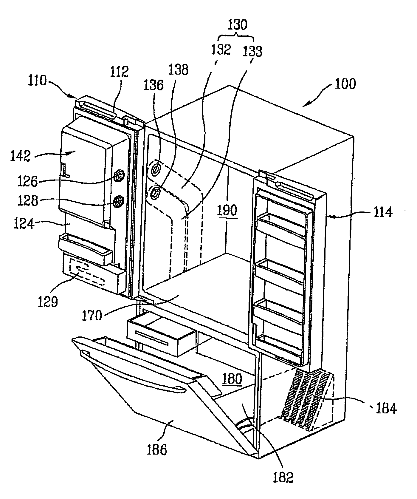
[0067]FIG. 4 is a perspective diagram of a refrigerator provided with a refrigerator door according to the present invention.

[0068]Referring to FIG. 4, a refrigerator body 100 has a rectangular box shape of which front side is selectively open. An inside of the body 100 is partitioned into an upper part and a lower part by a partition wall 170 to configure a cold storage room 190 and a freezer room 180, respectively.

[0069]And, refrigerator doors 110, 114 and 186 are provided to the open front side of the body 100, i.e., open front sides of the cold storage room 190 and the freezer rooms 180. The refrigerator doors 110, 114 and 186 include cold storage doors 110 and 114 selectively opening / closing the cold st...


PUM


Abstract

A refrigerator door is provided. The refrigerator door has an outer case forming a shape of the refrigerator door, an inner case provided within the outer case to configure a backside of the refrigerator door wherein a space between the inner case and the outer case is charged with a foaming liquid, an ice making unit provided to one side of the inner case to make ice, a fixing unit provided to the space charged with the foaming liquid between the inner case and the outer case and fixing the ice making unit to the refrigerator door, and a dispenser provided to one side of the outer case to discharge the ice supplied by the ice making unit.

Description

[0001]This application claims the benefit of the Korean Patent Applications No. 10-2005-0088914 filed on Sep. 23, 2005, No. 10-2005-0109425 filed on Nov. 16, 2005, No. 10-2005-0127516 filed on Dec. 22, 2005 and No. 10-2005-0134683 filed on Dec. 30, 2005, which are hereby incorporated by reference as if fully set forth herein.BACKGROUND OF THE INVENTION[0002]1. Field of the Invention[0003]The present invention relates to a refrigerator, and more particularly, to a refrigerator door. Although the present invention is suitable for a wide scope of applications, it is particularly suitable for facilitating an icemaker unit to be installed to prevent water from splashed on the refrigerator door, filing the door with a foaming liquid and enabling cold air of a refrigerator to flow to an ice-making room without leaking.[0004]2. Discussion of the Related Art[0005]Generally, a refrigerator is a device for storing food at low temperature. And, the refrigerator is a home appliance storing food ...

Claims


Application Information

Patent Timeline
Patent Type & Authority Applications(United States)
IPC IPC(8): F25C5/18F25D23/02F25D25/00B67D7/80
CPCF25C5/005F25C1/00F25C2500/06F25D17/065F25D23/02F25D23/126F25D2317/062F25D2317/0664F25D2317/067F25D2323/122F25D2400/40E05D11/0081E05Y2800/10E05Y2900/31F25C2400/14F25C5/22
Inventor LEE, BOK DONGLEE, SEUNG MOKPARK, SAM KYU
Owner LG ELECTRONICS INC
Why Eureka
Try Eureka