
Image forming apparatus

a technology of forming apparatus and forming chamber, which is applied in the direction of electrographic process apparatus, instruments, optics, etc., can solve the problems of inability heavy load on the scanner portion, and becoming difficult to secure a space, so as to facilitate the opening/closing of the exterior portion and reduce the size of the space for opening/closing

Active Publication Date: 2009-07-09
KYOCERA DOCUMENT SOLUTIONS INC
View PDF7 Cites 19 Cited by
  • Summary
  • Abstract
  • Description
  • Claims
  • Application Information

AI Technical Summary

Benefits of technology

[0022]According to the above image forming apparatus, an openable exterior portion has a plurality of panels. Therefore, it is possible to reduce the size of a space required when the openable exterior portion is opened. Furthermore, according to the above image forming apparatus, with an opening / closing operation of any one of the panels, the other panels are opened / closed by an opening / closing interlocking device.
[0024]Therefore, according to the above image forming apparatus, it is possible to reduce the size of a space for opening / closing the exterior portion and also to facilitate opening / closing of the exterior portion.

Problems solved by technology

With the recent downsizing or the like of the image forming apparatuses, it is becoming difficult to secure a space which allows the exterior portion to be opened and closed.
For example, in an image forming apparatus where a scanner is provided above a paper discharge tray portion, it is not possible to secure a space for opening / closing an exterior portion because the scanner is an obstacle to that.
However, the scanner portion is a heavy load.
Therefore, the method of the above patent documents has a problem of placing a heavy burden on the user when the scanner portion is opened / closed.
This poses another problem of requiring additional measures such as enhancing strength of the hinge portion.

Method used


Image

  • Image forming apparatus
  • Image forming apparatus
  • Image forming apparatus

Examples


Embodiment Construction

[0031]Hereunder is a description of an image forming apparatus according to one embodiment of the present invention. In the following drawings, scales of respective members are appropriately modified for easy recognition of the respective members. Furthermore, in the following description, a multifunction device provided with a plurality of functions such as that of a printer and a copy machine will be described as one example of an image forming apparatus according to the present invention.

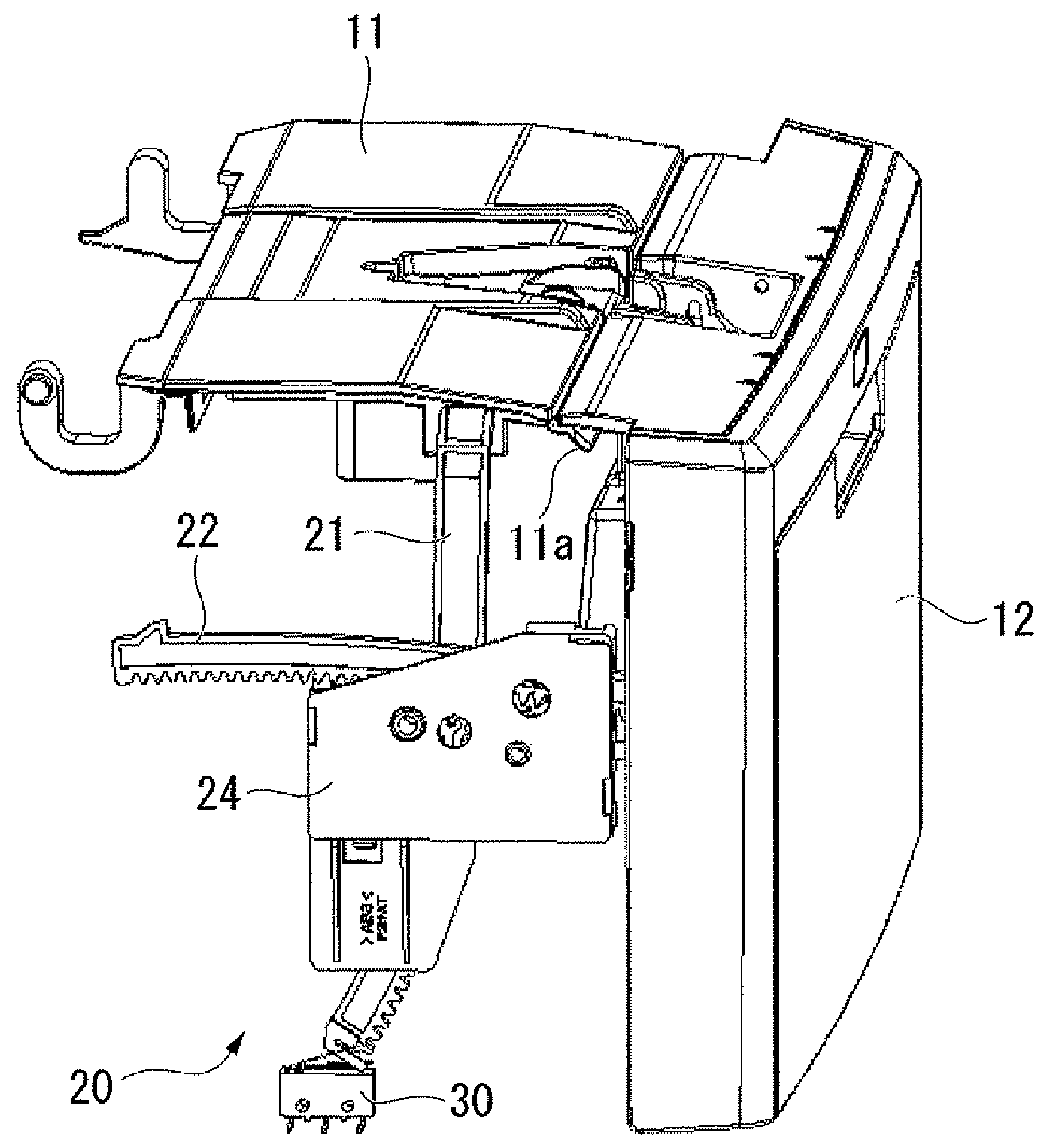
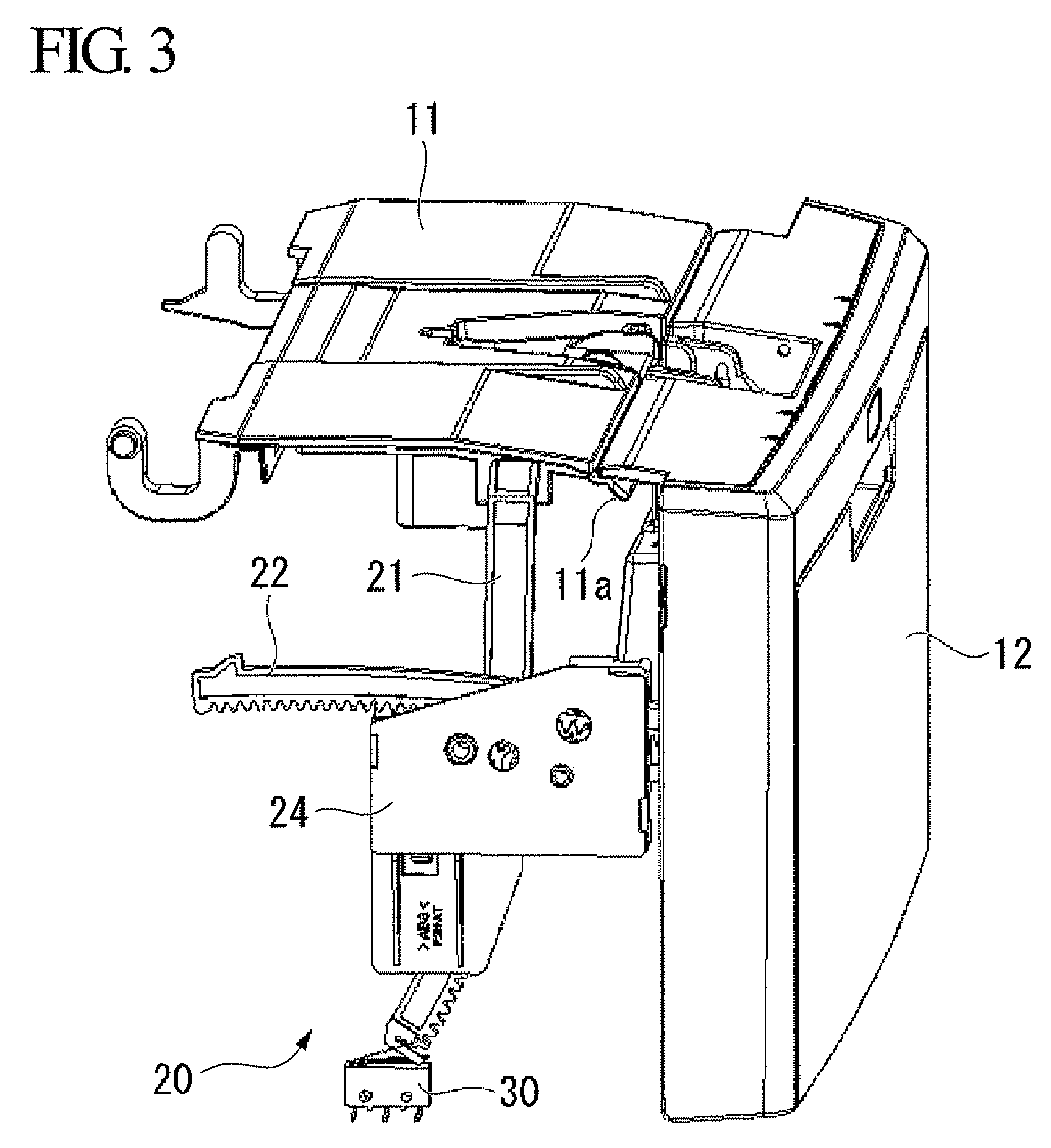
[0032]FIG. 1 and FIG. 2 are perspective views of a multifunction device S1 of the present embodiment. FIG. 1 is a perspective view showing the multifunction device S1 a cover portion 10 (exterior portion) closed. FIG. 2 is a perspective view showing the multifunction device S1 with the cover portion 10 opened.

[0033]The multifunction device S1 uses an image creation unit 2 (internal mechanism for image formation) contained in an interior of a main unit 1 to perform printing on a recording sheet. T...


PUM


Abstract

An image forming apparatus, including: an exterior portion having a first panel and a second panel that are opened / closed when an internal mechanism for image formation is taken outside; and an opening / closing interlocking device that makes the second panel open / close in connection with an opening / closing operation of the first panel.

Description

[0001]Priority is claimed on Japanese Patent Application No. 2008-001412, filed on Jan. 8, 2008, the contents of which are incorporated herein by reference.BACKGROUND OF THE INVENTION[0002]1. Field of the Invention[0003]The present invention relates to an image forming apparatus including an exterior portion that opens and closes when an internal mechanism for image formation is taken outside.[0004]2. Description of the Related Art[0005]In image forming apparatuses such as printers and copy machines, an internal mechanism can be taken out from the apparatus to clear a paper jam inside, or for maintenance or replacement of the internal mechanism.[0006]To be more specific, such an image forming apparatus includes an exterior portion that is openably provided. Opening the exterior portion exposes the internal mechanism.[0007]With the recent downsizing or the like of the image forming apparatuses, it is becoming difficult to secure a space which allows the exterior portion to be opened ...

Claims


Application Information

Patent Timeline
Patent Type & Authority Applications(United States)
IPC IPC(8): G03G15/00
CPCG03G21/1633G03G2221/169
Inventor TSUCHIYA, HIROAKI
Owner KYOCERA DOCUMENT SOLUTIONS INC
Learn More