
Generating apparatus using magnetic induction to generate electrical energy to provide illuminating function

a technology of electrical energy and generating apparatus, which is applied in the direction of dynamo-electric components, dynamo-electric machines, cycle equipments, etc., can solve the problems of environmental pollution, decrepit bicycle travel speed, and waste of natural sources

Inactive Publication Date: 2009-07-09
CHUEN TERS IND
View PDF14 Cites 6 Cited by
  • Summary
  • Abstract
  • Description
  • Claims
  • Application Information

AI Technical Summary

Benefits of technology

[0005]In accordance with the present invention, there is provided a generating apparatus in combination of a bicycle, comprising an induction unit secured on a fixed mandrel of a bicycle, and a magnetic unit secured on a rotation member of the bicycle to rotate with the rotation member of the bicycle and to rotate relative to the induction unit to produce a magnetic induction effect between the induction unit and the magnetic unit.
[0007]Another objective of the present invention is to provide a generating apparatus for a bicycle, wherein when the magnetic unit is rotatable relative to the induction unit, the magnets of the magnetic unit are movable relative to the induction coil of the induction unit to produce a magnetic induction effect instantaneously between the induction coil of the induction unit and the magnets of the magnetic unit, so that the induction coil of the induction unit produces an induction electrical energy under action of the successive mutual interaction of the magnetic lines of force of the north poles and the south poles of the magnets of the magnetic unit to supply an electric power to the lamp of the bicycle so as to provide an illuminating function.
[0008]A further objective of the present invention is to provide a generating apparatus for a bicycle, wherein the generating apparatus can generate an electric power successively by rotating the magnetic unit relative to the induction unit, without needing any external energy source and without producing any pollution, thereby saving the natural source and achieving an environmental protection.
[0009]A further objective of the present invention is to provide a generating apparatus for a bicycle, wherein the induction unit is mounted on the fixed mandrel of the bicycle, and the magnetic unit is mounted on the rotation member of the bicycle, so that the generating apparatus is mounted on the bicycle easily and quickly, thereby facilitating a user mounting the generating apparatus.
[0010]A further objective of the present invention is to provide a generating apparatus for a bicycle, wherein a distance is defined between the induction unit and the magnetic unit, so that the induction unit is spaced from the magnetic unit and will not interfere with rotation of the rotation member of the bicycle and movement of the bicycle.

Problems solved by technology

However, the generating apparatus is in contact with the wheel of the bicycle so that the generating apparatus will interfere with rotation of the wheel of the bicycle, thereby decreasing the travel speed of the bicycle.
However, the battery easily wastes the natural source and causes an environmental pollution.

Method used


Image

  • Generating apparatus using magnetic induction to generate electrical energy to provide illuminating function
  • Generating apparatus using magnetic induction to generate electrical energy to provide illuminating function
  • Generating apparatus using magnetic induction to generate electrical energy to provide illuminating function

Examples


Embodiment Construction

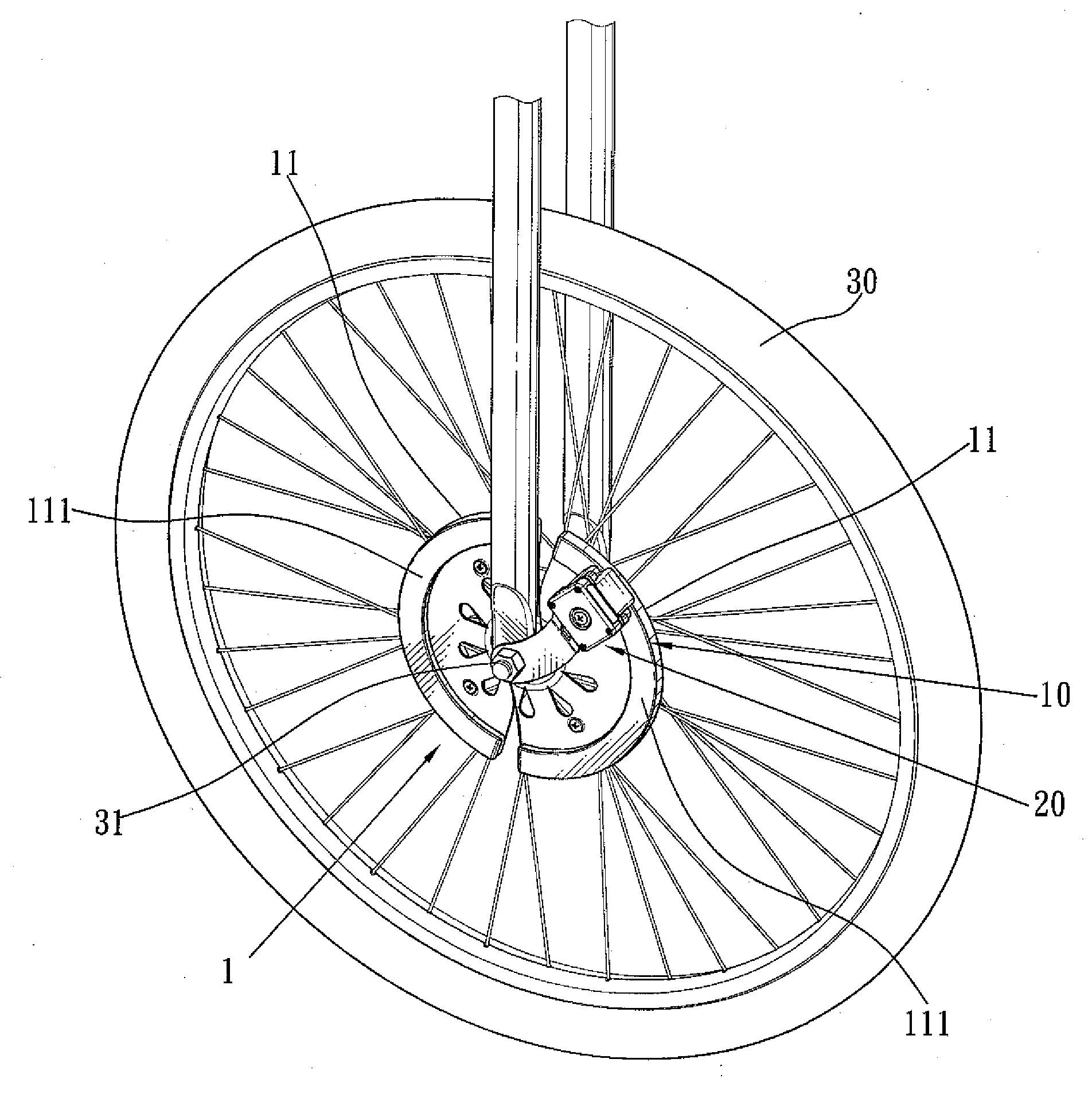
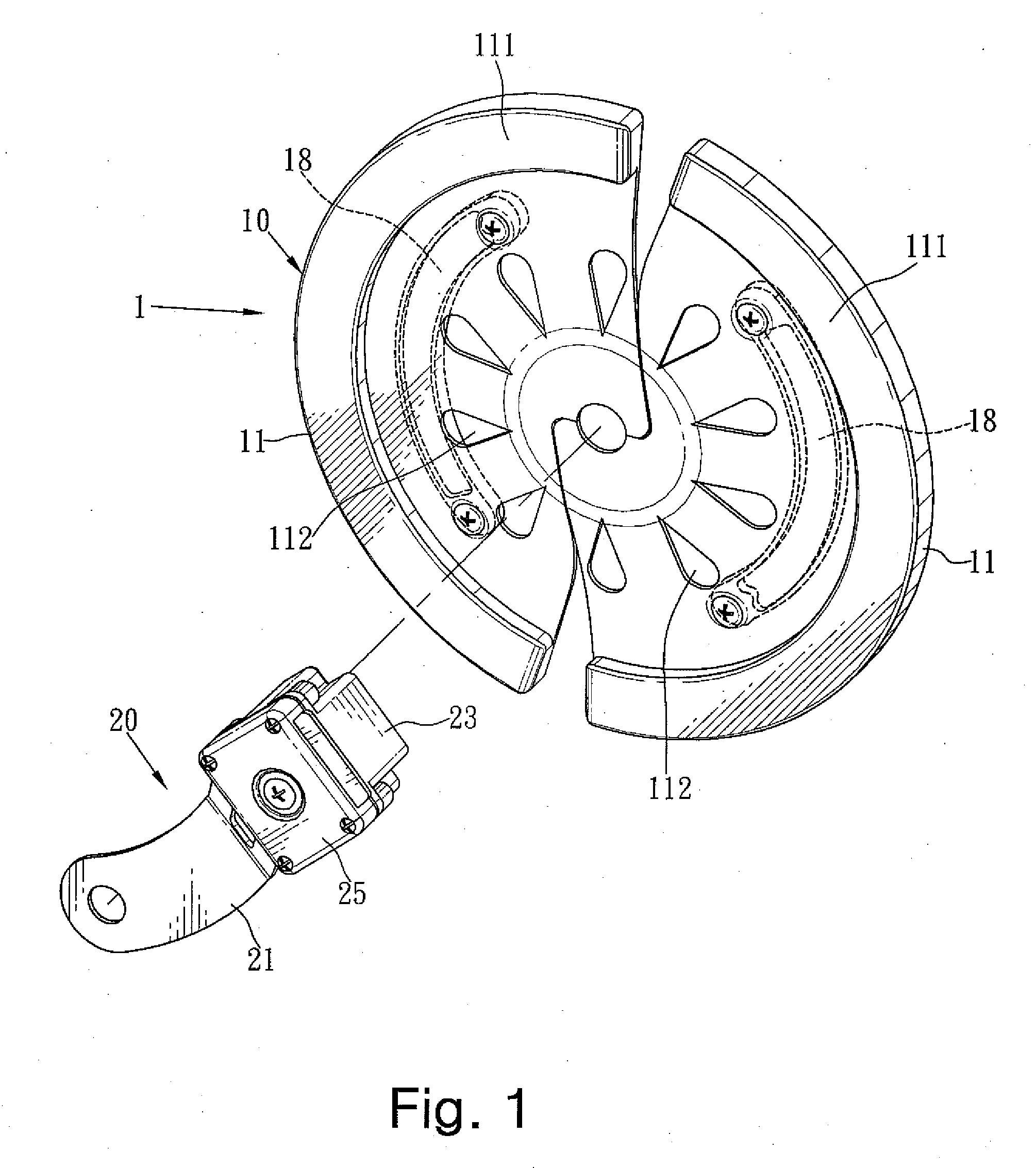
[0019]Referring to the drawings and initially to FIGS. 1-5, a generating apparatus for a bicycle in accordance with the preferred embodiment of the present invention comprises an induction unit 20 secured on a fixed mandrel 31 of a bicycle, and a magnetic unit 1 secured on a rotation member 30 of the bicycle to rotate with the rotation member 30 of the bicycle and to rotate relative to the induction unit 20 to produce a magnetic induction effect between the induction unit 20 and the magnetic unit 1.

[0020]The rotation member 30 of the bicycle is a wheel.

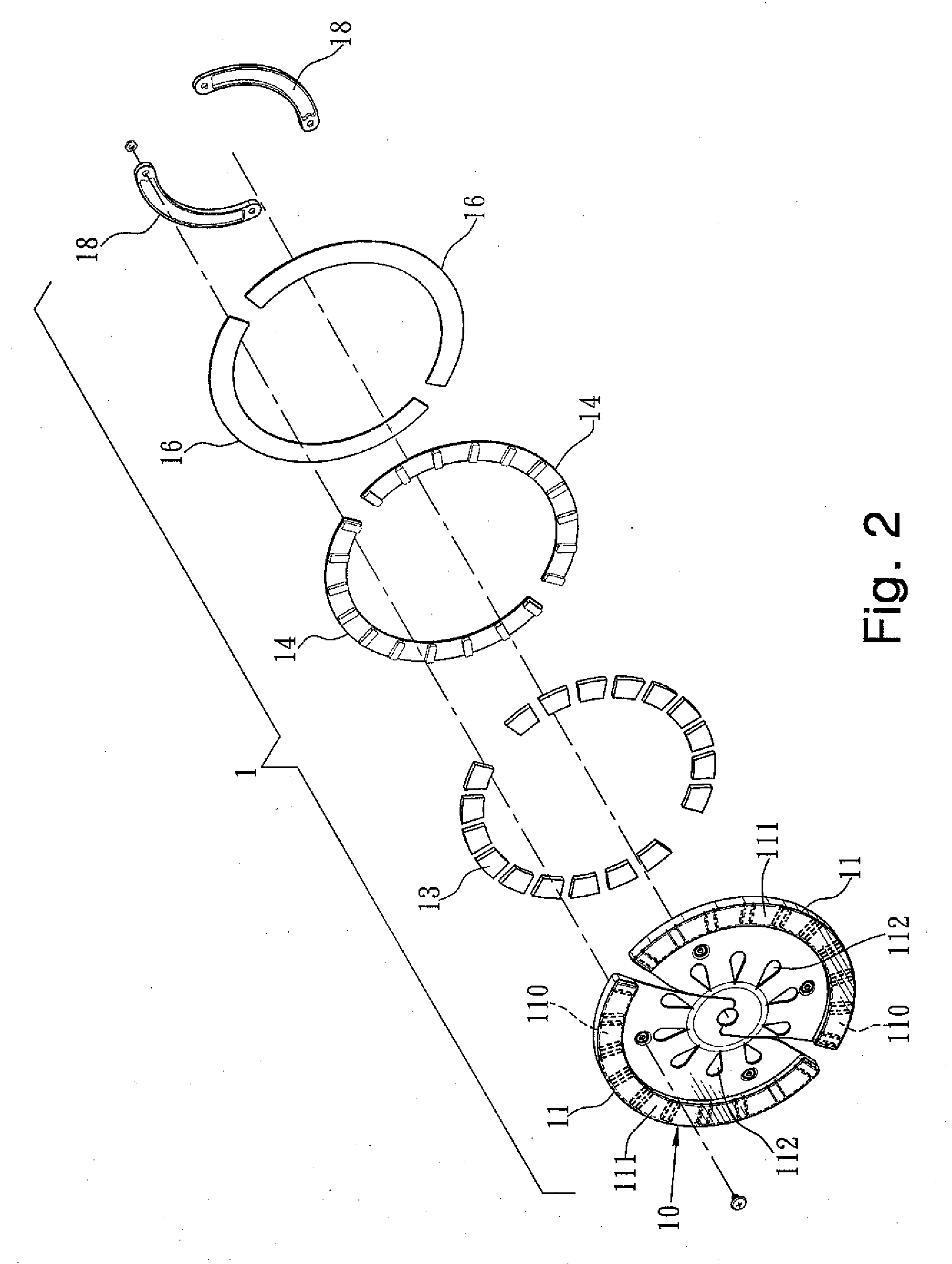
[0021]The magnetic unit 1 includes a disk 10 secured on the rotation member 30 of the bicycle to rotate with the rotation member 30 of the bicycle, and a plurality of magnets 13 mounted on an outer periphery of the disk 10 and are arranged in an annular shape. Each of the magnets 13 of the magnetic unit 1 has a north pole “N” and a south pole “S”, and the north poles “N” and the south poles “S” of the magnets 13 of the magnetic unit 1...


PUM


Abstract

A generating apparatus includes an induction unit secured on a fixed mandrel of a bicycle, and a magnetic unit secured on a rotation member of the bicycle. Thus, when the magnetic unit is rotatable relative to the induction unit, the magnets of the magnetic unit are movable relative to the induction coil of the induction unit to produce a magnetic induction effect, so that the induction coil of the induction unit produces an induction electrical energy under action of the successive mutual interaction of the magnetic lines of force of the north poles and the south poles of the magnets of the magnetic unit to supply an electric power to the lamp of the bicycle so as to provide an illuminating function.

Description

BACKGROUND OF THE INVENTION[0001]1. Field of the Invention[0002]The present invention relates to a generating apparatus and, more particularly, to a generating apparatus for a bicycle.[0003]2. Description of the Related Art[0004]A conventional generating apparatus for a bicycle can generate an electric power by a rubbing action of a wheel of the bicycle to supply the electric power to a lamp of the bicycle so as to provide an illuminating function. However, the generating apparatus is in contact with the wheel of the bicycle so that the generating apparatus will interfere with rotation of the wheel of the bicycle, thereby decreasing the travel speed of the bicycle. On the other hand, a battery can be used to supply an electric power to the lamp of the bicycle so as to provide an illuminating function. However, the battery easily wastes the natural source and causes an environmental pollution.BRIEF SUMMARY OF THE INVENTION[0005]In accordance with the present invention, there is provi...

Claims


Application Information

Patent Timeline
Patent Type & Authority Applications(United States)
IPC IPC(8): H02K7/18B62J6/12
CPCH02K7/1869B62J6/12
Inventor LIN, MING-CHUAN
Owner CHUEN TERS IND
Learn More