
Image generation apparatus and image generation method

a technology of image generation apparatus and image, which is applied in the field of image generation apparatus, can solve the problems of high device cost, separate adjustment of imaging device properties, and increase in the cost of photographing apparatus, and achieve the effect of improving spatial and temporal resolution

Inactive Publication Date: 2009-07-02
SOVEREIGN PEAK VENTURES LLC
View PDF6 Cites 57 Cited by
  • Summary
  • Abstract
  • Description
  • Claims
  • Application Information

AI Technical Summary

Benefits of technology

The image generation apparatus described in this patent can create a new video with better resolution and smoother motion even when there are areas of the original video that don't have accurate information. It can also take the best parts of multiple video sequences to create a new video with all the benefits of each.

Problems solved by technology

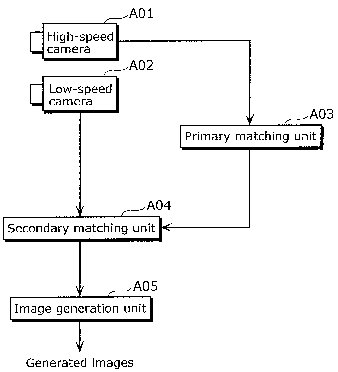
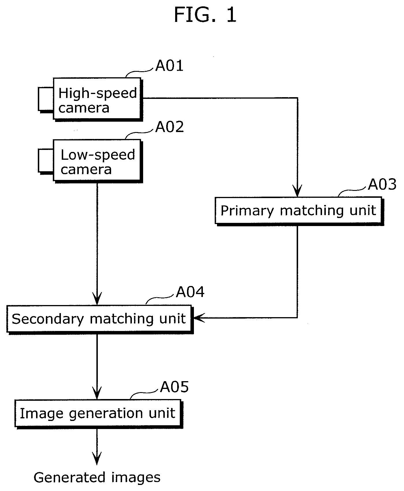
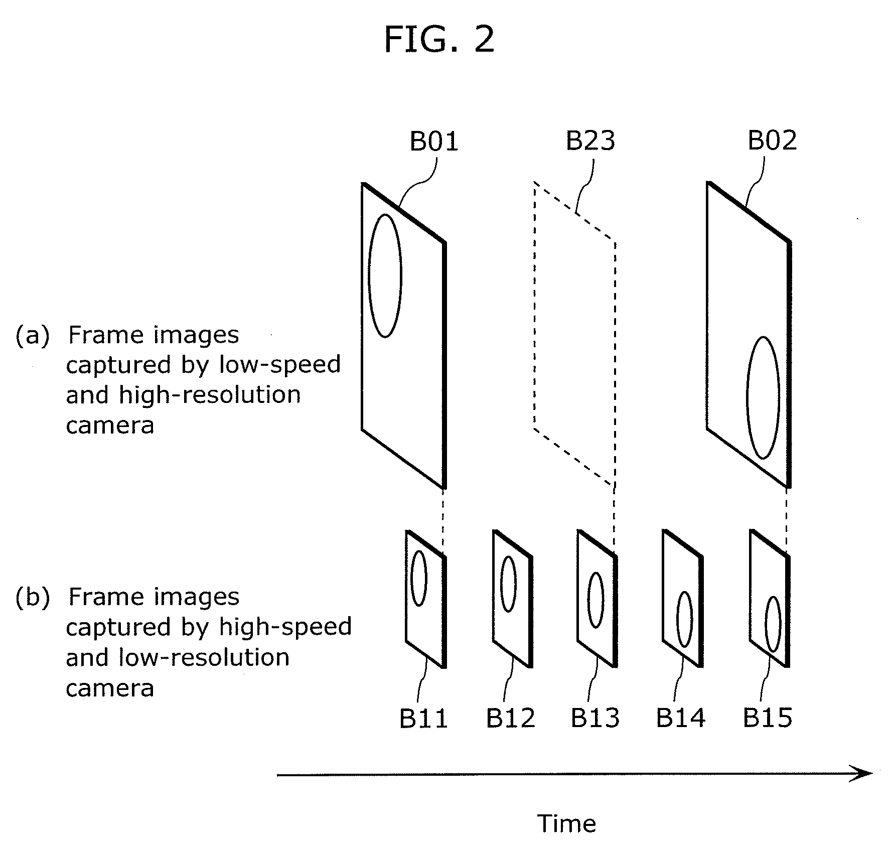
The technical problem addressed in this patent is the need for a method to obtain high-resolution images that move smoothly at a high speed, without the need for a special imaging device or increased cost. The conventional method of capturing high-resolution images requires a high-speed camera, which is expensive or requires adjustments to the properties of the camera to transfer the image information in parallel. The patent proposes a method for generating high-resolution intermediate frame images using a high-speed and low-resolution camera and a low-speed and high-resolution camera, based on the detected correspondence of pixels between frames and the positional relationship between pixels in adjacent frames.

Method used


Image

  • Image generation apparatus and image generation method
  • Image generation apparatus and image generation method
  • Image generation apparatus and image generation method

Examples


embodiment

[0083]An image generation system according to the preferred embodiment of the present invention will be described in detail with reference to the diagrams.

[0084]FIG. 3 is a block diagram which shows the hardware structure of the image generation system according to the present embodiment of the present invention.

[0085]An image generation system 100 is a system for generating a new high spatial and temporal resolution video sequence (a high-speed and high-resolution video sequence in this example) from a plurality of video sequences (a high-speed and low-resolution video sequence and a low-speed and high-resolution video sequence) showing the same object. This system includes an image capturing apparatus 10, an image storage apparatus 20, an image generation apparatus 30 and a display apparatus 40. The image capturing apparatus 10 is a camera or the like which photographs an object so as to capture two types of video sequences of different spatial and temporal resolutions (a high-spe...


PUM


Abstract

Provided is an image generation apparatus that generates a new video sequence from video sequences including image regions for which corresponding point detection and motion estimation cannot be performed correctly. The image generation apparatus includes: an exposure control unit (105) which controls an image capturing apparatus (10) to temporally change an exposure amount in a part of an exposure period; an image receiving unit (101) which receives the first video sequence and the second video sequence captured under the control of the exposure control unit (105); an image integration unit (104) which generates, from these video sequences, the new video sequence having a resolution equal to or higher than the second resolution, at a frame rate equal to or higher than the first video sequence, by reducing a difference between (i) a value of each frame in the second video sequence and (ii) a sum of values of frames in the new video sequence which correspond to the second exposure period for the each frame in the second video sequence. The second video sequence has higher resolution than the first video sequence, and the second video sequence has a frame exposure time period longer than the first video sequence.

Description


Claims


Application Information

Patent Timeline
Owner SOVEREIGN PEAK VENTURES LLC
Learn More