
Mouse with scanning module

a scanning module and mouse technology, applied in the field of mouse with scanning module, can solve the problems of large size of typical scanner, inconvenient portability, and resul

Inactive Publication Date: 2009-07-02
HON HAI PRECISION IND CO LTD
View PDF3 Cites 0 Cited by
  • Summary
  • Abstract
  • Description
  • Claims
  • Application Information

AI Technical Summary

Benefits of technology

[0004]With the increasing popularity of personal computers, peripheral devices, such as mice and scanners, are frequently enhanced. A mouse is used to control the coordinates of a cursor on the computer screen, while a scanner is used to generate a digital representation of an image for data input to the personal computer. However, a typical scanner is large in size and, as a result, not very portable.

Problems solved by technology

However, a typical scanner is large in size and, as a result, not very portable.

Method used


Image

  • Mouse with scanning module
  • Mouse with scanning module
  • Mouse with scanning module

Examples


Embodiment Construction

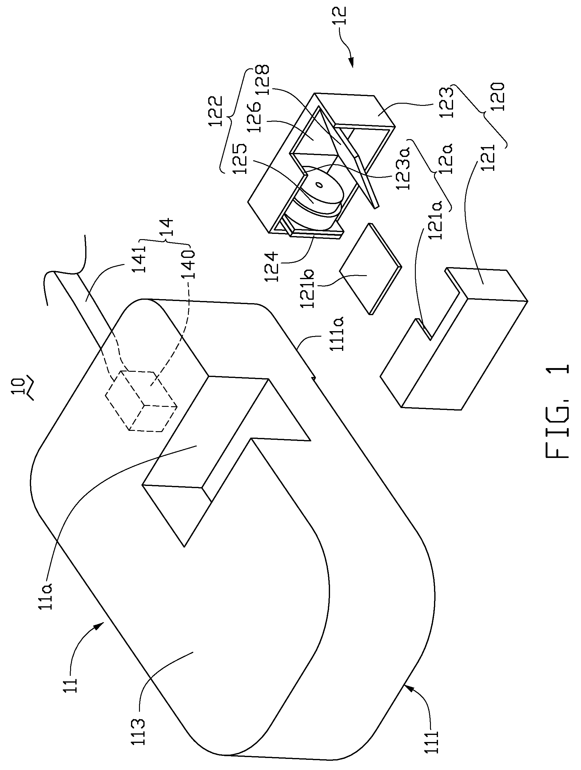
[0008]Referring to FIG. 1, a mouse 10 according to a first embodiment is shown. The mouse 10 includes a body 11, a scanner 12, and a data sending module 14. The data sending module 14 is received in the body 11. In this embodiment, the data sending module 14 includes a control circuit 140 and a cable 141. One end of the cable 141 is electrically connected to the control circuit 140, while the other end is electrically connected to a host of a personal computer (not shown). The control circuit 140 is configured for receiving data and sending out data via the cable 141. In other embodiments, the data sending module 14 may include a control circuit and a wireless sending unit, wherein the control circuit is configured for receiving the data and the wireless sending unit is configured for sending out the data wirelessly.

[0009]The body 11 includes a first surface 111, and a second surface 113 opposite to the first surface 111. The body 11 further defines a recess 11a on the second surfac...


PUM


Abstract

A mouse includes a body, and a scanner. The body includes a first surface, an opposite second surface, and a recess defined in the second surface. The scanner received in the recess includes a housing defining a scanning window, an optical scanning unit received in the housing and an imaging sensor package. The optical scanning unit includes a light source for emitting light through the scanning window towards an object to be scanned, a reflector for reflecting light from the object, and a lens module for focusing the reflected light from the object. The imaging sensor package is received in the housing and is configured for receiving the focused light and generating image data associated with the object.

Description

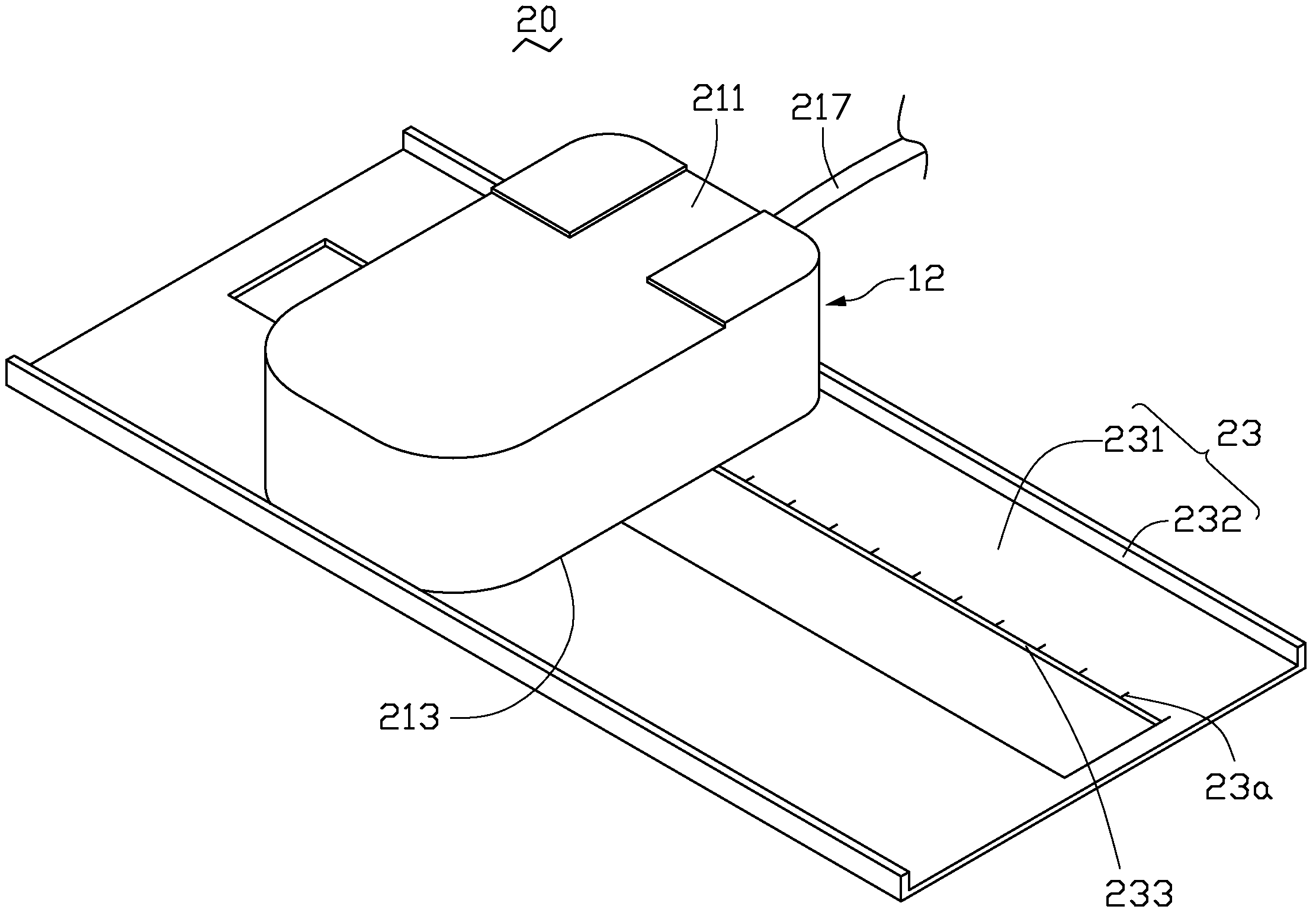
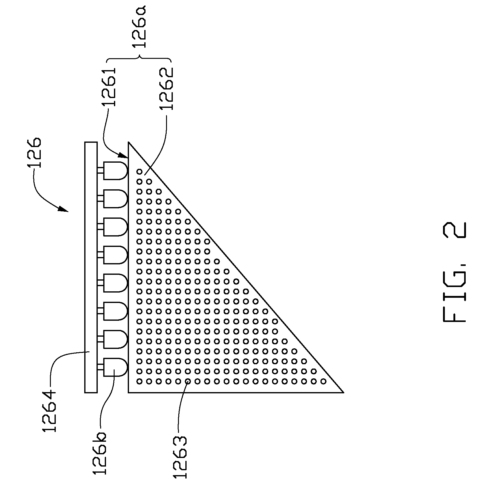
BACKGROUND[0001]1. Field of the Invention[0002]The present invention relates to a mouse with a scanning module.[0003]2. Description of the Related Art[0004]With the increasing popularity of personal computers, peripheral devices, such as mice and scanners, are frequently enhanced. A mouse is used to control the coordinates of a cursor on the computer screen, while a scanner is used to generate a digital representation of an image for data input to the personal computer. However, a typical scanner is large in size and, as a result, not very portable.BRIEF DESCRIPTION OF THE DRAWINGS[0005]FIG. 1 is a partially disassembled isometric view of a mouse according to a first embodiment, in which a scanner is implemented;[0006]FIG. 2 is a schematic view of a light source of the scanner of FIG. 1; and[0007]FIG. 3 is isometric view of a mouse according to a second embodiment.DETAILED DESCRIPTION[0008]Referring to FIG. 1, a mouse 10 according to a first embodiment is shown. The mouse 10 include...

Claims


Application Information

Patent Timeline
Patent Type & Authority Applications(United States)
IPC IPC(8): G06F3/033
CPCG06F3/03543H04N1/107H04N1/00541
Inventor CHANG, KENG-MING
Owner HON HAI PRECISION IND CO LTD
Learn More