
Lighting device having illumination, backlighting and display applications

a backlighting and display technology, applied in the direction of discharge tube/lamp details, discharge tube luminescnet screens, instruments, etc., can solve the problem of reducing performance (intensity) and efficiency, reducing the total luminance output, and similar self-absorption problems

Active Publication Date: 2009-07-02
GE LIGHTING SOLUTIONS LLC
View PDF3 Cites 34 Cited by
  • Summary
  • Abstract
  • Description
  • Claims
  • Application Information

AI Technical Summary

Problems solved by technology

Self-absorption in a lighting device generally occurs when light emissions stay within the device to excite other phosphors, and be absorbed or otherwise prevented from exiting the device, thus reducing performance (intensity) and efficiency.
However, overlapping of phosphor excitation and emitting spectra, which is the main condition for the self-absorption, reduces the total luminance output.
It also has the similar self-absorption problem.
However, the approach cannot suppress self-absorption significantly because, for example, 50% of the emitted green light will be directed to a red phosphor layer, despite that the red phosphor layer is located closer to LED light engine.

Method used


Image

  • Lighting device having illumination, backlighting and display applications
  • Lighting device having illumination, backlighting and display applications
  • Lighting device having illumination, backlighting and display applications

Examples


Embodiment Construction

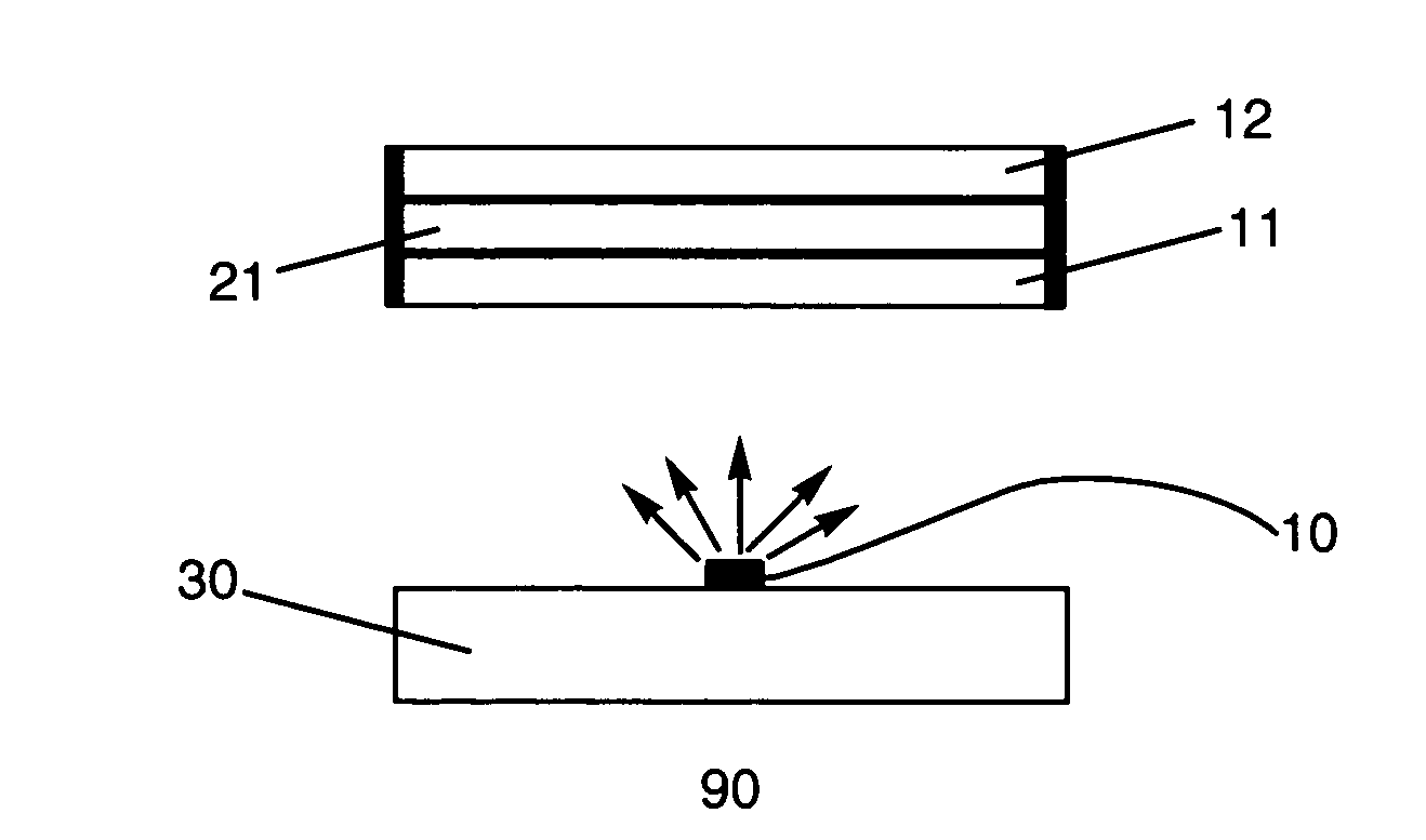
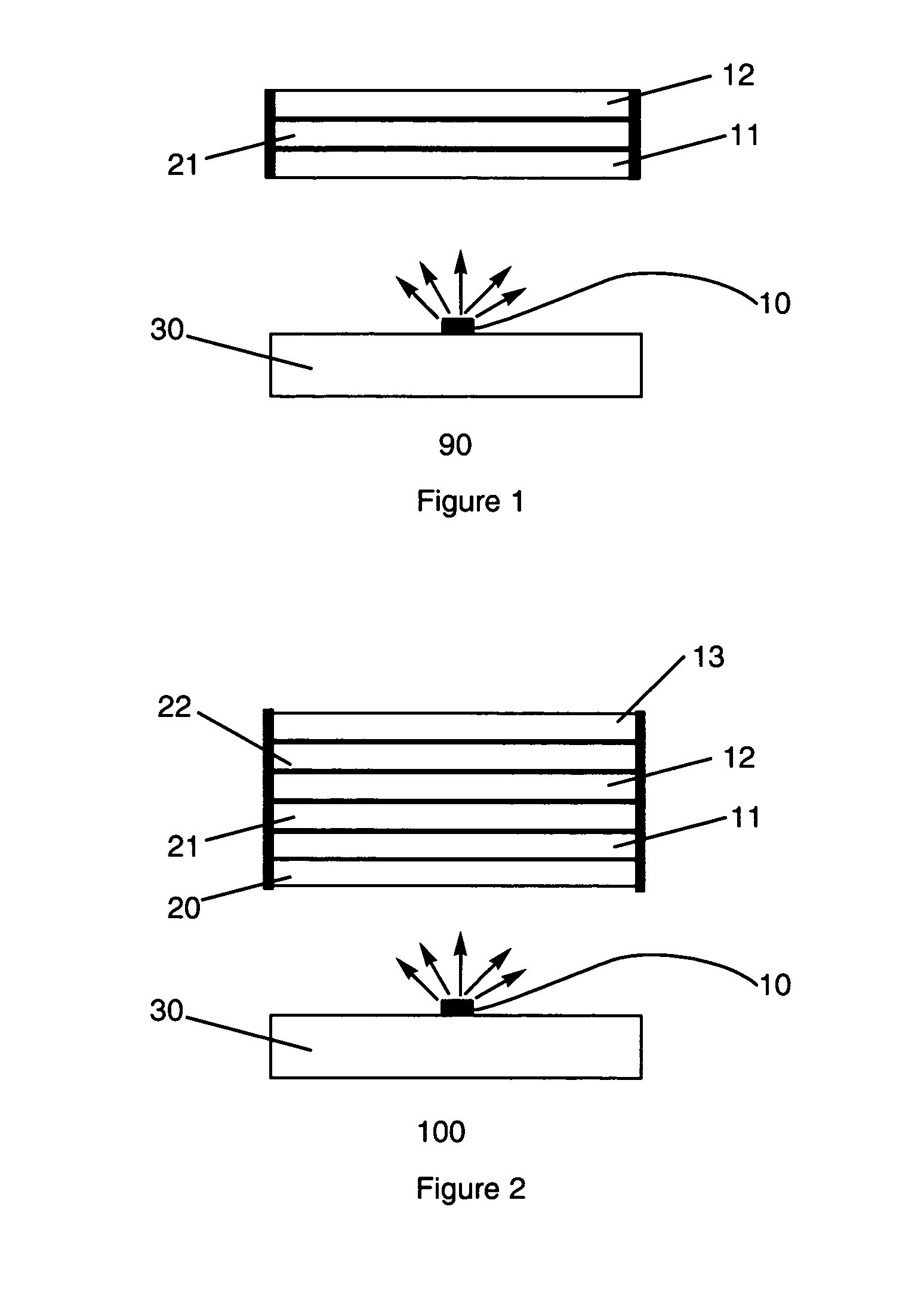
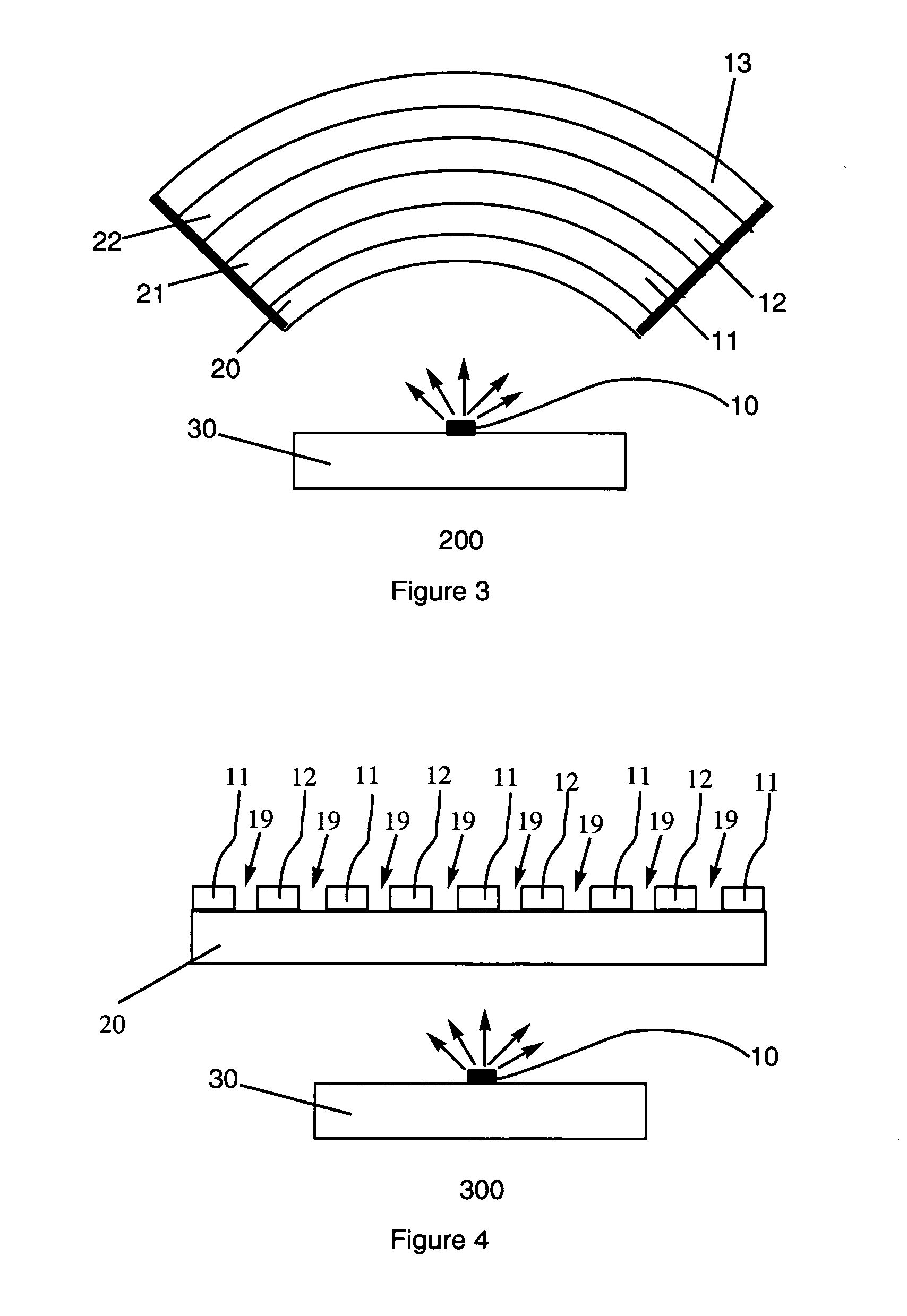
[0022]With reference to FIG. 1, a lighting device 90 includes one or more radiation sources 10 such as a laser diode (LD) or a lighting emitting diode (LED) mounted on a support member 30, a first wavelength converting member 11, and a second wavelength converting member 12. A first selective reflector 21 is placed between the two wavelength converting members and functions as a blocking optical element. The two wavelength converting members and the selective reflector are adapted in a vertical geometry. Wavelength converting member 11 and radiation source 10 may be separated by any media, or they may be contacted with each other directly (not shown). In operation state, first wavelength converting member 11 absorbs at least a portion of the electromagnetic radiation originated from radiation source 10, and emits a first electromagnetic radiation with peak wavelength λe1; second wavelength converting member 12 absorbs at least a portion of the electromagnetic radiation originated fr...


PUM


Abstract

Provided are a lighting device, a backlighting device, and a display device that comprise a radiation source such as LED and wavelength converting members comprising phosphors. In one embodiment, self-absorption within the devices is suppressed or reduced by placing a selective reflector between two wavelength converting members, and the wavelength converting member emitting light with longer peak wavelength is substantially isolated from the irradiation of another wavelength converting member emitting light with shorter peak wavelength. In other embodiments, the wavelength converting members are arranged in strip configuration; or in adjacent hexagons configuration.

Description

BACKGROUND OF THE INVENTION[0001]The present invention is generally related to a lighting device, a backlighting device, and a display device with improved efficiency. The invention can be applied to light emitting devices such as general lighting of phosphor lamp, lighting for signals or automobiles, backlight for LCDs, and displays.[0002]Self-absorption in a lighting device generally occurs when light emissions stay within the device to excite other phosphors, and be absorbed or otherwise prevented from exiting the device, thus reducing performance (intensity) and efficiency. For example, white light is produced for the different applications using down converting phosphors together with suitable light engines. Typical spectral range for light engines now is about 390-460 nm, a near UV-blue spectral region. Two ways are known to produce white light using phosphor down converting process. One way is that a LED blue light engine interacts with so-called “yellow” type phosphor and su...

Claims


Application Information

Patent Timeline
Patent Type & Authority Applications(United States)
IPC IPC(8): H01J1/62
CPCG02F1/133603G02F2001/133614H01J1/63H01L33/504H01L2924/0002H01L33/60H01L2924/00G02F1/133614
Inventor KOLODIN, BORISAANEGOLA, SRINATHRADKOV, EMIL VERGILOV
Owner GE LIGHTING SOLUTIONS LLC
Learn More