
System, method and apparatus for providing direct current

a direct current and system technology, applied in the field of power supplies, can solve the problems of high cost and loss, and the dc voltage that is typically utilized is not easily and/or efficiently derived from these ac voltages, and the cost of both solutions is high and the loss is larg

Inactive Publication Date: 2009-07-02
ADVANCED ENERGY IND INC
View PDF10 Cites 28 Cited by
  • Summary
  • Abstract
  • Description
  • Claims
  • Application Information

AI Technical Summary

Benefits of technology

[0005]Exemplary embodiments of the present invention that are shown in the drawings are summarized below. These and other embodiments are more fully described in the Detailed Description section. It is to be understood, however, that there is no intention to limit the invention to the forms described in this Summary of the Invention or in the Detailed Description. One skilled in the art can recognize that there are numerous modifications, equivalents and alternative constructions that fall within the spirit and scope of the invention as expressed in the claims.
[0006]In one exemplary embodiment, the present invention may be characterized as an apparatus comprising a rectifier configured to rectify an alternating-current (AC) voltage so as to generate a first direct-current (DC) voltage and a regulator including a first, second, and third outputs, the first and second outputs configured to connect to a first load and the second and third outputs configured to couple to a second load. The regulator in this embodiment is configured to apply, using the first direct-current voltage, a regulated second DC voltage between the firs

Problems solved by technology

But the DC voltages that are typically utilized are not easily and / or efficiently derived from these AC voltages.
Both of these solutions, however, are expensive and lossy.

Method used


Image

  • System, method and apparatus for providing direct current
  • System, method and apparatus for providing direct current
  • System, method and apparatus for providing direct current

Examples


Embodiment Construction

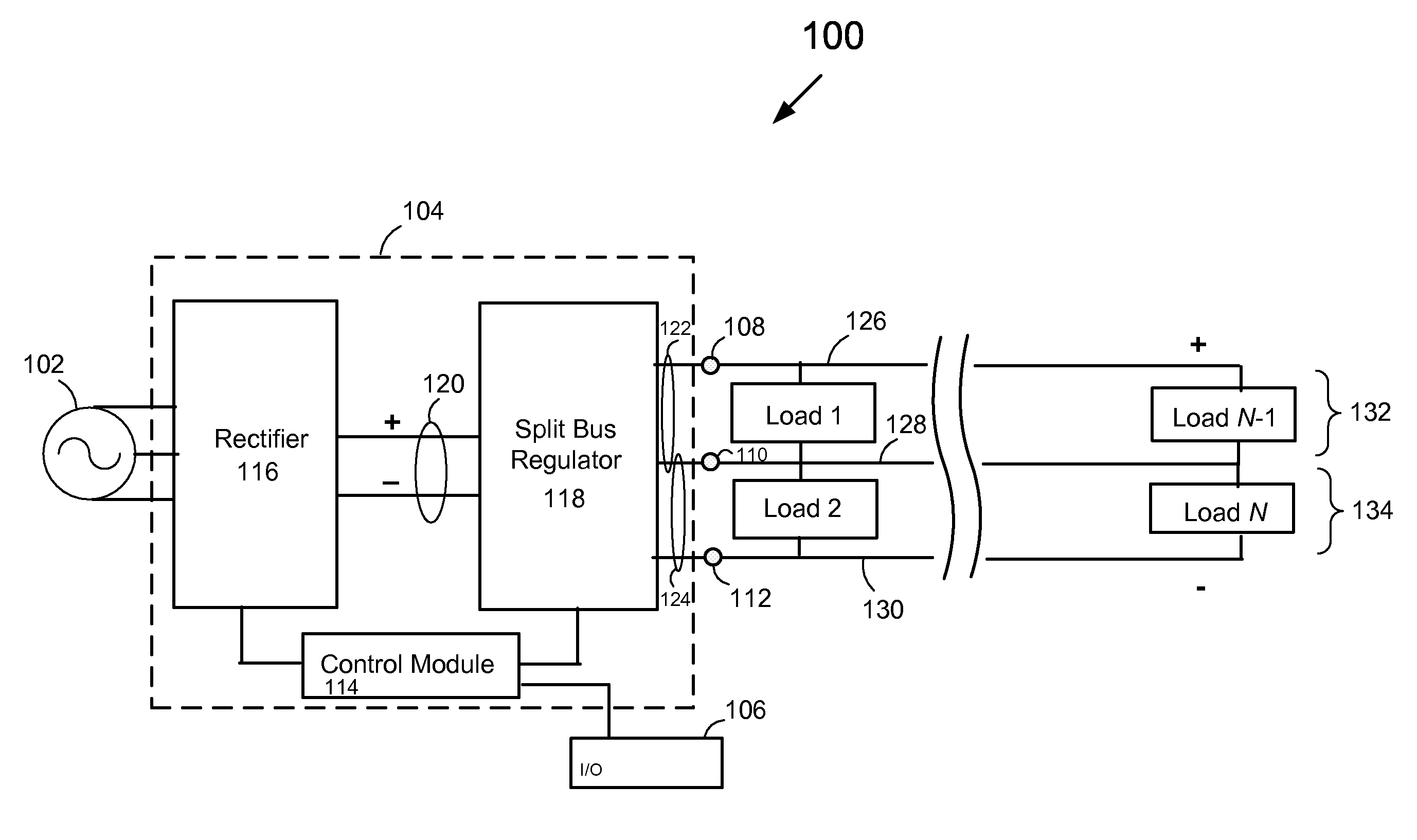
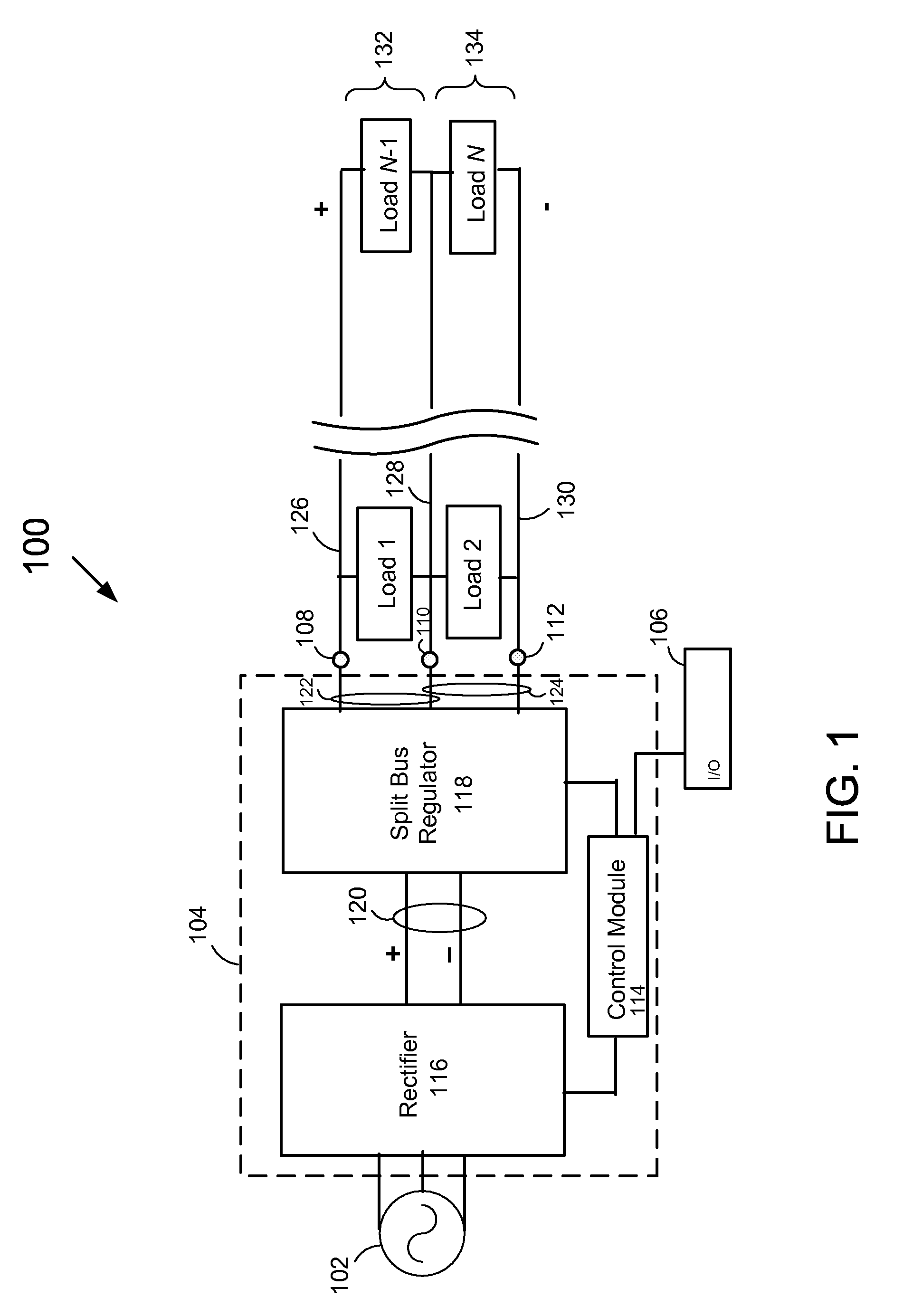
[0017]Referring now to the drawings, where like or similar elements are designated with identical reference numerals throughout the several views, and referring in particular to FIG. 1, it is a block diagram 100 depicting an exemplary embodiment of the present invention. Shown are an AC source voltage 102, a DC power supply 104 that is coupled to both an in input / output (I / O) module 106 and N loads via three outputs 108, 110, 112. The DC power supply 104 in this embodiment includes a control module 114 coupled to the I / O module 106, a rectifier 116 and a split bus regulator 118.

[0018]The magnitude of the AC source voltage 102 that is applied to the rectifier 116 may vary depending upon the originator of the AC source voltage 102. In North America, power is often distributed at 480 AC, and in Europe power is frequently distributed at 400 AC volts while in Asia 380 volts AC is a common distribution voltage. In some embodiments for example, the AC power source is a 4-wire wye-configure...


PUM


Abstract

A system and method for providing direct-current power is described. In one embodiment a direct current voltage is converted into at least two regulated DC voltages, and a first of the at least two regulated DC voltages is applied across a first and second outputs and a second of the at least two regulated DC voltages is applied across the second output and a third output. And when a first impedance across the first and second outputs is less than a second impedance across the second and third outputs, current is received via the second output while delivering power to the first and second impedances.

Description

FIELD OF THE INVENTION[0001]The present invention relates to power supplies. In particular, but not by way of limitation, the present invention relates to systems and methods for providing regulated direct current.BACKGROUND OF THE INVENTION[0002]There are currently many systems that operate under direct current (DC) power, and many additional systems that operate under alternating current (AC) power that may be converted to operate under DC power due to benefits in cost, voltage regulation tolerances and energy efficiency.[0003]For example, power provided to processing tools for flat-panel processing and semiconductor processing may be distributed by DC systems. In addition, power distribution for data centers (e.g., server farms), commercial buildings and military applications may be best suited to DC power distribution.[0004]Power, however, is typically distributed by utilities at AC voltages that requires high power conversion from AC to DC voltages. Most commonly, service entra...

Claims


Application Information

Patent Timeline
IPC IPC(8): H02J1/04
CPCH02J1/08H02M3/1584Y02B70/1466H02M2001/007H02M2001/009H02M3/1588H02M1/007H02M1/009Y02B70/10
Inventor SEYMOUR, ERIC
Owner ADVANCED ENERGY IND INC
Learn More