Ball screw device

Inactive Publication Date: 2009-07-02
JTEKT CORP
View PDF4 Cites 28 Cited by
  • Summary
  • Abstract
  • Description
  • Claims
  • Application Information

AI Technical Summary

Benefits of technology

[0008]A ball screw device according to the invention includes: a screw shaft; a ball screw nut engaged with the screw shaft with balls interposed between the ball screw nut and the screw shaft; a stopper that determines a limit of movement of the screw shaft in a forward direction when the ball screw nut is rotated to cause the screw shaft to move rectilinearly in the forward direction along an axial direction; and a braking portion that reduces a speed of the forward movement of the screw shaft before the screw shaft reaches the limit.
[0011]The braking portion is not for stopping the screw shaft, but for reducing the impact load at the time of the impact of the stopper. The range of travel in the braking portion is shorter than the range of travel of the stopper so that the impact of the stopper occurs after the screw shaft travels over the range of travel in the braking portion. Although the screw shaft rectilinearly moves fast when a large force is applied to the screw shaft in the axial direction, the screw shaft that is moving forward fast receives a force, of which the direction is opposite to the moving direction, from the braking portion. Thus, the speed of the rectilinear movement (forward movement speed) of the screw shaft is reduced, so that the rotational speed of the ball screw nut is reduced and the rotational inertial force of the ball screw nut is reduced. Then, the screw shaft is forcibly stopped by the stopper. At this time, the rotational inertial force of the ball screw nut has already been reduced, and the occurrence of brinelling in a raceway of the ball screw is prevented. After the screw shaft is forcibly stopped by the stopper, the screw shaft is returned to the original state.
[0013]It is preferable that the hollow shaft be made of metal and double as a rotor of a motor. The small diameter portion of the hollow shaft can be formed by tapering the end portion of the hollow shaft in such a manner that the inner diameter of the hollow shaft gradually decreases toward the forward direction of the screw shaft. The tip portion of the screw shaft may either be tapered or not be tapered, that is, may be straight. The buffer layer is, for example, formed on an outer circumferential surface of the tip portion of the screw shaft, but may be provided on the inner circumferential surface of the hollow shaft. For example, the small diameter portion of the hollow shaft may be formed by applying resin, in a tapered form, to the inner surface of the cylindrical rotor of the motor, and such a resin layer may be used also as the buffer layer. When a large force is applied to the screw shaft in the axial direction, the screw shaft is fitted into the small diameter portion of the hollow shaft, and the speed of the forward movement of the screw shaft is reduced. Thus, the rotational speed of the ball screw nut is reduced, and the rotational inertial force of the ball screw nut is reduced. The buffer layer reduces the impact when the screw shaft is fitted into the small diameter portion of the hollow shaft, and facilitates returning the screw shaft into the original state. The material for the buffer layer is typically polyurethane, polyamide, or the like, for example. However, it is also possible to use, for example, a paper material for the buffer layer. The buffer layer also provides a function of preventing the ball screw nut from falling off the screw shaft.
[0014]The braking portion may include an elastic member. The braking portion may further include a support portion that is fixed so that a relative position between the ball screw nut and the support portion in the axial direction is invariable, and the elastic member may be provided on at least one of the support portion and the screw shaft. The elastic member may be provided on the support portion and may receive the screw shaft that is moving in the forward direction. When the elastic member is provided on the support portion side, the weight of the screw shaft, which is a movable portion, is not increased, and in addition, it is possible to minimize the possibility of the occurrence of a problem such as falling off. The braking portion may include an air damper that receives the screw shaft that is moving in the forward direction. Examples of the elastic member include various types of springs and an elastic body made of rubber or synthetic resin.
[0018]With the ball screw device of the invention, it is possible to reduce the impact load when the screw shaft is forcibly stopped, and it is therefore possible to prevent the occurrence of brinelling in a raceway of the ball screw. Thus, a problem is solved that the moment of inertia increases when the overall size of the ball screw device is enlarged to obtain a high strength, and it is therefore possible to reduce the size and weight of the ball screw device.

Problems solved by technology

When this occurs, if the speed of the screw shaft is fast, the rotational inertial force of the nut is large at the time of sudden stop of the screw shaft, and therefore, brinelling in a raceway of the ball screw can occur.

Method used


Image

  • Ball screw device
  • Ball screw device
  • Ball screw device

Examples


first embodiment

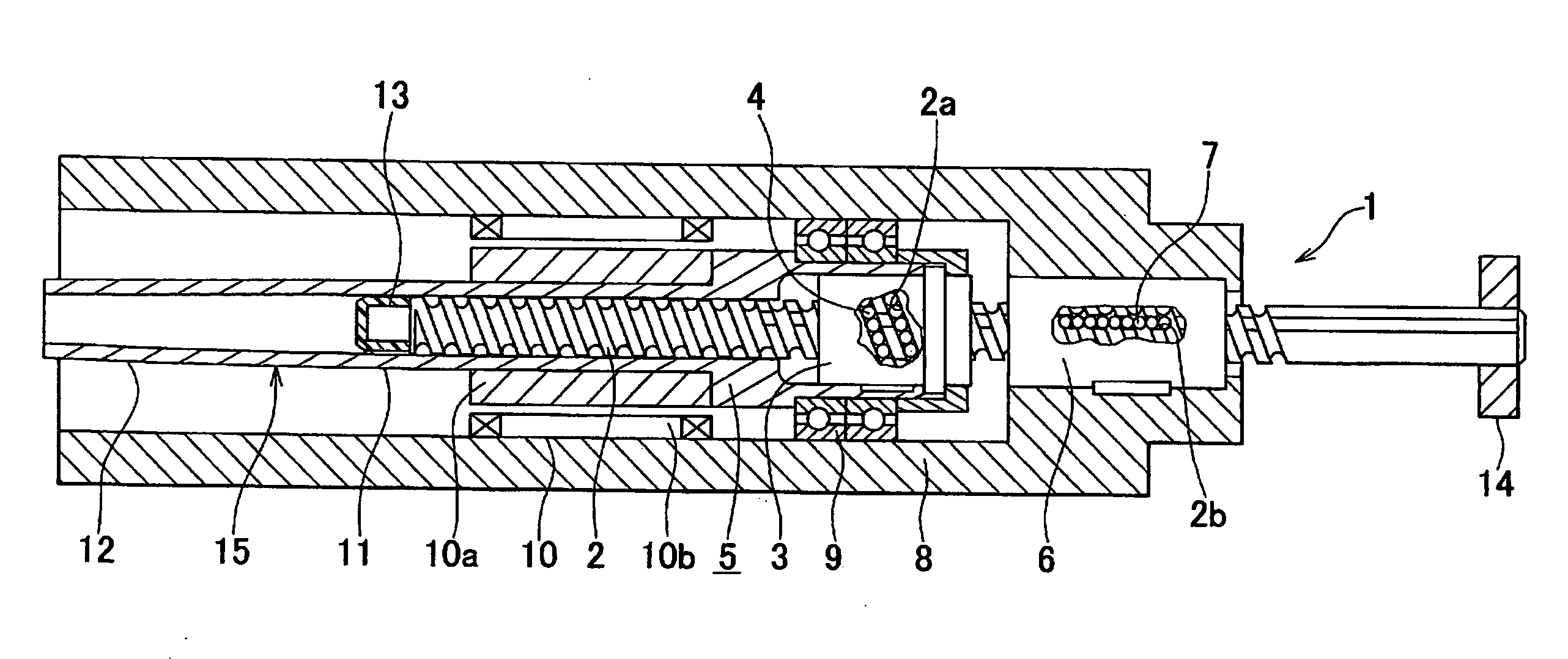
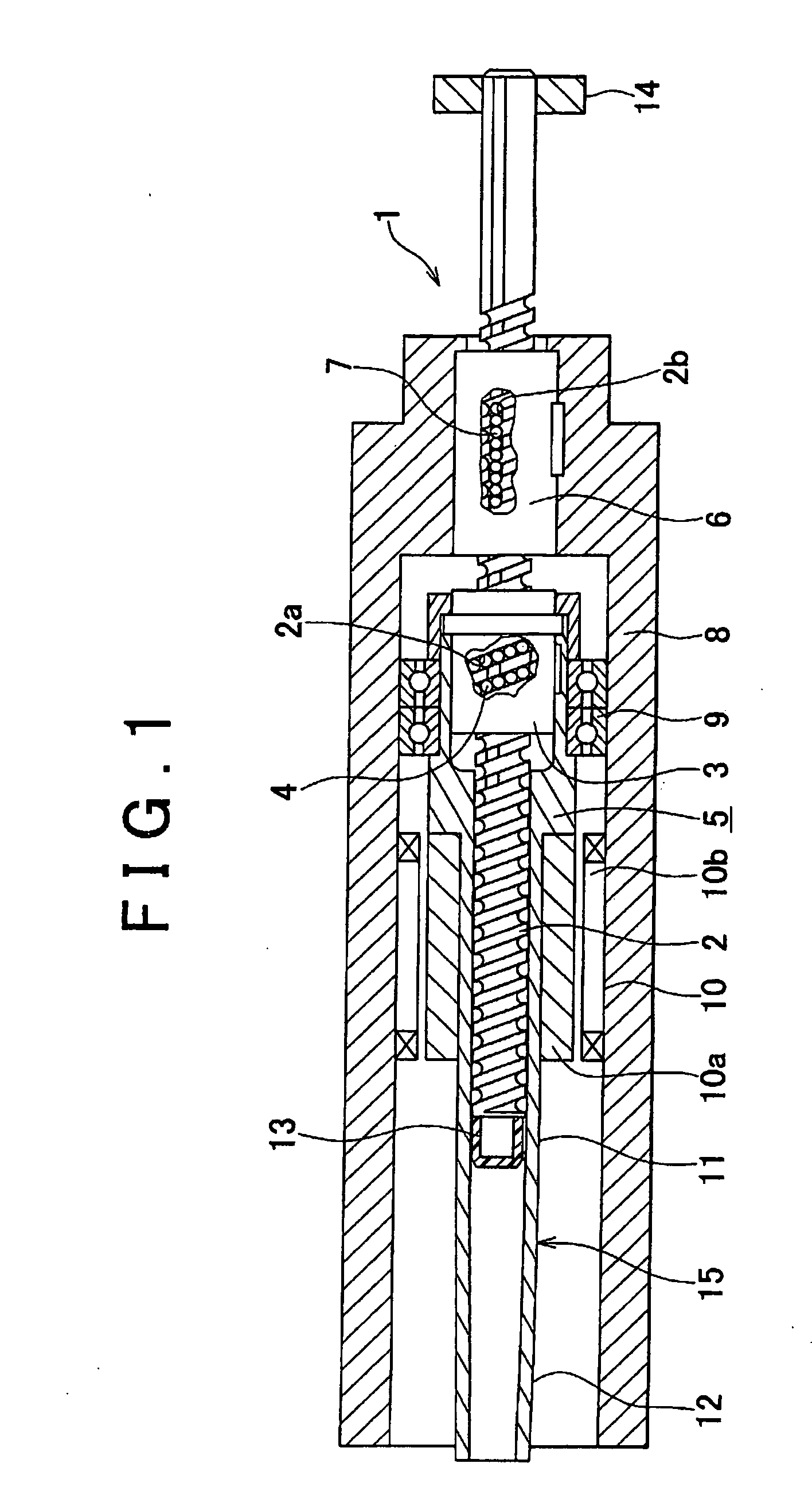
[0027]FIG. 1 shows a ball screw device according to the invention.

[0028]The ball screw device 1 includes: a steel screw shaft 2, extending in the right-and-left direction, that is provided with a thread groove 2a and a spline groove 2b extending in the right-and-left direction; a ball screw nut 3 engaged with the thread groove 2a of the screw shaft 2 with balls 4 interposed therebetween; a hollow shaft 5 integrated with the ball screw nut 3 and extending to the left; a ball spline outer cylinder 6 that is engaged with the spline groove 2b of the screw shaft 2 with balls 7 interposed therebetween and guides the right and left (axial) rectilinear motion of the screw shaft 2; a housing 8 that rotatably supports the hollow shaft 5 through bearings 9 and fixedly supports the ball spline outer cylinder 6; a motor 10 including a magnet (rotor) 10a fixed on an outer circumferential surface of the hollow shaft 5 and a stator 10b fixed on the inner circumferential surface of the housing 8 so ...

third embodiment

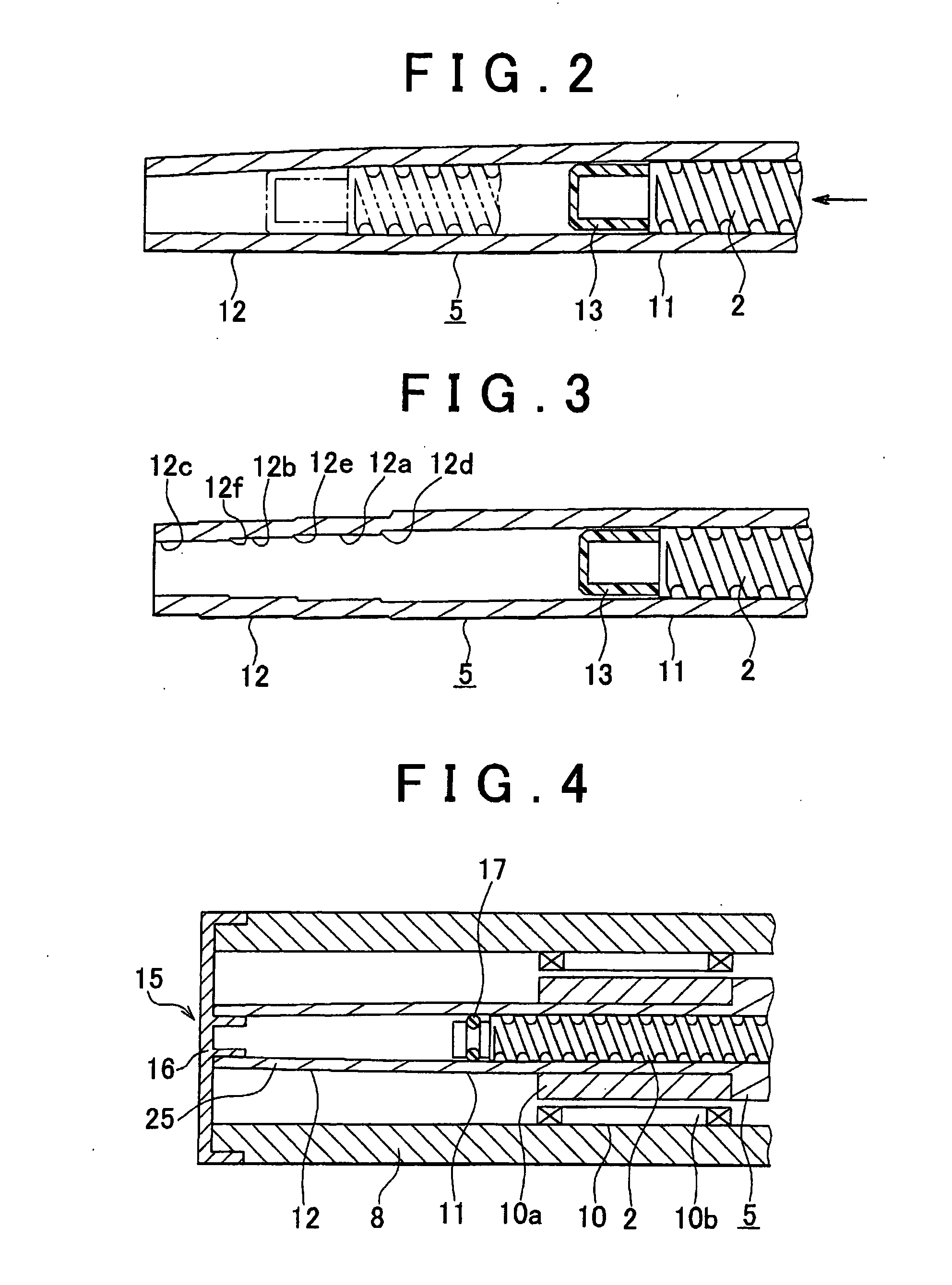
[0039]FIG. 4 shows the ball screw device according to the invention.

[0040]In FIG. 4, the braking means 15 includes: the small diameter portion 12 of the hollow shaft 5 that is tapered such that the inner diameter of the small diameter portion 12 is gradually reduced and the inner diameter of the end portion of the small diameter portion 12 is smaller than the outer diameter of the tip portion of the screw shaft 2; a cover 16 that is fixed to an end portion of the housing 8 and closes the opening at the tip of the hollow shaft 5; and an O ring (annular seal member) 17 provided on a tip portion of the screw shaft 2. In the braking means 15, the opening at the tip of the small diameter portion 12 of the hollow shaft 5 is closed by the cover 16 to form a closed-end cylinder, and the tip portion of the screw shaft 2 with the O ring 17 acts as a piston, whereby an air damper 25 is created.

[0041]According to the ball screw device 1 of the third embodiment, before the stopper 14 hits the ho...

fourth embodiment

[0042]FIG. 5 shows the ball screw device according to the invention, in which an elastic member is used in the braking means 15.

[0043]In FIG. 5, the hollow shaft 5 has a constant diameter also in the end portion, and the braking means 15 includes: the cover 16 that is fixed to an end portion of the housing 8 and closes the opening at the tip of the hollow shaft 5; and an elastic body (elastic member) 18, made of polyurethane foam, that is provided on the cover 16 and receives the tip portion of the screw shaft 2.

[0044]According to the screw device 1 of the fourth embodiment, before the stopper 14 hits the housing 8, the end portion of the screw shaft 2 hits the elastic body 18, whereby a force is applied that is directed opposite to the direction in which the screw shaft 2 is moving. As a result, the speed of the forward movement of the screw shaft 2 is reduced, which results in reduction in the rotational speed of the motor 10. Thus, when the stopper 14 hits the housing 8, the iner...


PUM


Abstract

In a ball screw device, a ball screw nut is rotated, causing a screw shaft to rectilinearly move in the axial direction, and the limit of the movement of the screw shaft is determined by a stopper. The ball screw device includes a hollow shaft that rotates together with the ball screw nut and in which the screw shaft is movably fitted. The hollow shaft is provided with a small diameter portion that exerts a dragging force on the screw shaft before the screw shaft reaches the limit, and a buffer layer is formed on a tip portion of the screw shaft.

Description

INCORPORATION BY REFERENCE[0001]The disclosure of Japanese Patent Application No. 2007-335566 filed on Dec. 27, 2007 including the specification, drawings and abstract is incorporated herein by reference in its entirety.BACKGROUND OF THE INVENTION[0002]1. Field of the Invention[0003]The invention relates to a ball screw device, and in particular, to a ball screw device that is used in a form in which a screw shaft rectilinearly moves in the axial direction without rotation.[0004]2. Description of the Related Art[0005]A ball screw device that includes a screw shaft and a ball screw nut engaged with the screw shaft with balls interposed therebetween is often used as an electric actuator or in a damper. Japanese Patent Application Publication No. 2006-67649 (JP-A-2006-67649), for example, includes a description in which a ball screw device is used in a damper in which a screw shaft is connected to a motor, so that the screw shaft is rotated to cause a ball screw nut to rectilinearly mo...

Claims


Application Information

Patent Timeline
IPC IPC(8): F16H25/22
CPCF16H25/2015Y10T74/18576F16H25/2204
Inventor KOYAGI, KATSURAKAMIKAWA, TSUYOSHITACHI, TAKAYUKIKONDO, TAKUHIRO
Owner JTEKT CORP
Why Eureka
Try Eureka