Drilling tool

a drilling tool and tool body technology, applied in the field of drilling tools, can solve the problems of large interference between boxes of large dimensions, blockage of machines, and complex transmission

Active Publication Date: 2009-07-02
CIE DU SOL
View PDF23 Cites 13 Cited by
  • Summary
  • Abstract
  • Description
  • Claims
  • Application Information

AI Technical Summary

Benefits of technology

[0027]a mounting pad connected directly to the bottom end of said support means and fastened to the top end of the plate, the top edge face of the plate connecting said pad to the bearing-forming means having a special shape so that, in association with the small thickness of the plate, it is significantly easier to raise the tool when it is being used for digging a trench while mixing cuttings with another material.
[0028]It will be understood, that since the motors driving the cutters are disposed inside the cutters, the tool does not have a box containing the motor or bulky transmission systems. Furthermore, each motor can be controlled independently to give each pair of cutters a different speed of rotation. Since there is no box above the cutters of the tool, it can be understood that raising the tool through the mixture of drilling cuttings and hydraulic binder is made considerably easier. This is made easier still by the particular shape of the support structure having only an edge that is in a position to oppose the drilling tool being raised, and this edge has dimensions that are small and a shape that is appropriate.
[0030]Also preferably, the top edge face of the plate of the support means is chamfered. This further facilitates raising the drilling tool through the mixture of drilling cuttings and hydraulic binder.

Problems solved by technology

When the motor is mounted in a bulky box, the drawback presented by the machine consists in the box in which the motors are housed presenting a relatively large apparent area.
The presence of this box of large dimensions interferes considerably with raising the tool after it has performed the mixing, since the box needs to “barge through” the mixed material constituted by soil cuttings and hydraulic binder.
In some circumstances, while the machine is being raised, the presence of this box can lead to the machine becoming blocked in the panel filled with the mixture constituted by the drilling cuttings and the hydraulic binder.
The transmission is then complex and its efficiency mediocre.
However, if one pair of cutters becomes blocked, then all of the power from the motor must be absorbed by the other pair of cutters.
It is clear that such an excavator machine is totally incapable of mixing the cut soil with the hydraulic binder, so that the mixture is left in place in the portion of trench being dug in order to make the wall in the soil.

Method used


Image

  • Drilling tool
  • Drilling tool
  • Drilling tool

Examples


Embodiment Construction

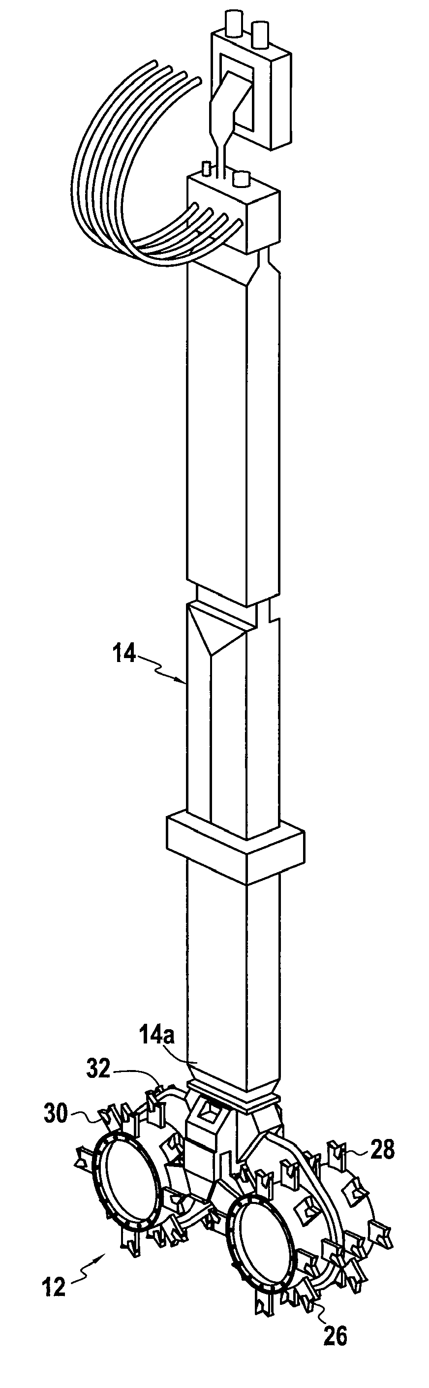
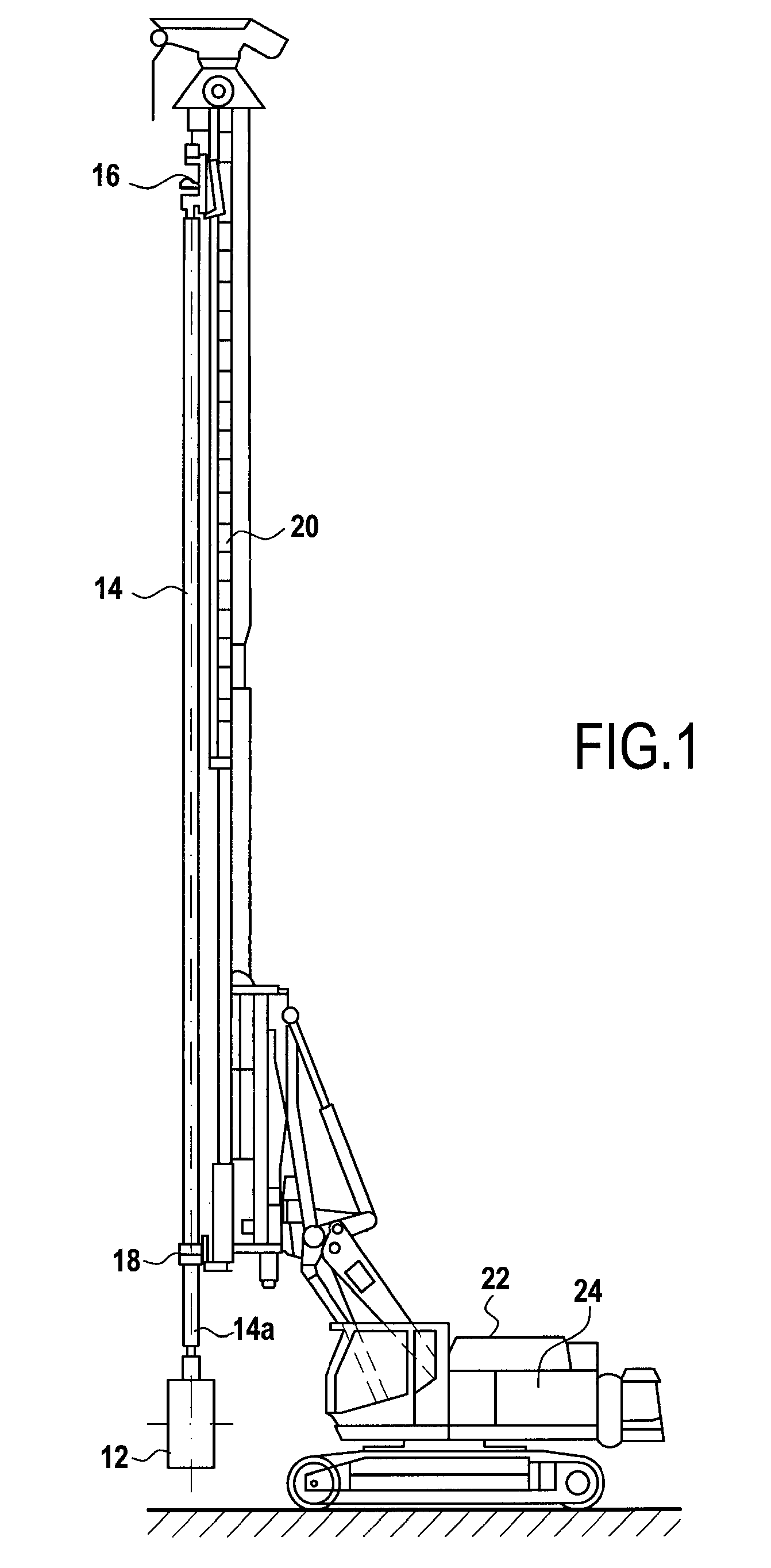
[0041]FIG. 1 shows a drilling machine using the drilling tool in accordance with the invention. The tool 12 is guided in the trench by a guide beam 14 of constant profile and preferably of rectangular right section. The tool 12 is fastened to the bottom end 14a of the beam. The guide beam 14 serves to transmit thrust forces and traction forces to the tool 12. It also serves to protect the pipes feeding the tool with hydraulic binder, together with the pipes powering the motors that drive rotation of the cutters. The guide beam 14 is connected by guide and drive means 16, 18 to a vertical mast 20. The mast is supported by a tracked vehicle 22 having installed thereon a system 24 for generating hydraulic power.

[0042]It will be understood that by causing the guide beam 14 to move upwards and downwards, the tool 12 is caused to move vertically in the soil so as to make a panel of a trench by drilling the soil and mixing the drilling cuttings with the hydraulic binder.

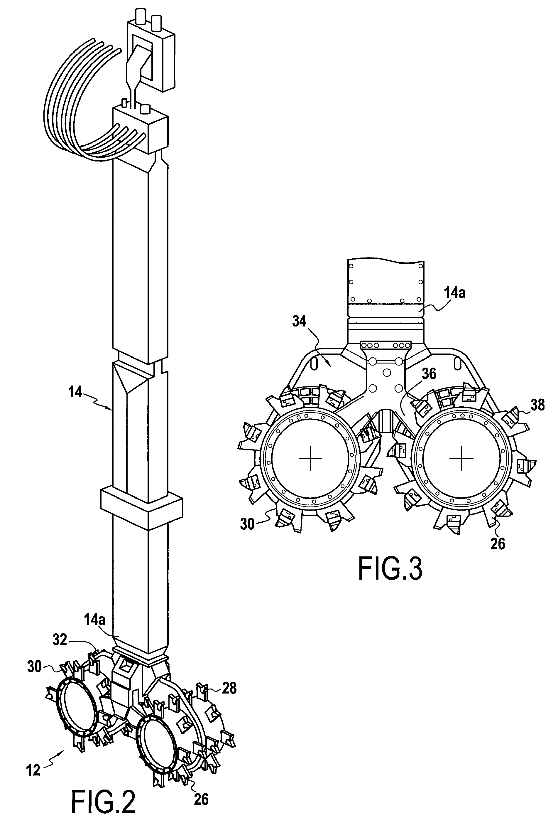
[0043]FIG. 2 shows ...


PUM


Abstract

The invention relates to a drilling tool comprising: two pairs of rotary drums in axial alignment on parallel axes; motor means for driving rotation of said drums; support means; and a support structure on which said drums are mounted to rotate and serving to connect said drums to the support means; said tool being characterized in that said motor means are mounted inside the drums; and in that said support structure comprises a plate forming bearings at its bottom ends for said drum; and a mounting pad for fastening to the support means, the top edge face of the plate connecting said pad to the bearing-forming means.

Description

[0001]This is a 371 national phase application of PCT / FR2007 / 051062 filed 4 Apr. 2007, claiming priority to French Patent Application No. FR 0651240 filed 6 Apr. 2006, the contents of which are incorporated herein by reference.FIELD OF THE INVENTION[0002]The present invention relates to a drilling tool, particularly but not exclusively for making walls in the soil as obtained by mixing the cut soil with an additional binder.BACKGROUND OF THE INVENTION[0003]Soil mixing techniques whereby drilled ground is mixed in situ with a hydraulic binder are nowadays commonly used for improving substructures. The tools used generally employ special equipment resembling augers that are caused to rotate about a vertical axis. Those machines enable rectangular wall elements to be made by juxtaposing a plurality of augers, thereby requiring high-power machines to be used whenever the trench needs to reach depths greater than 10 meters (m).[0004]A new type of machine has been in existence for several...

Claims


Application Information

Patent Timeline
IPC IPC(8): E02F3/20E02F3/24E02D17/13E02D3/12
CPCE02D5/18E02F3/205E02D17/13
Inventor CHAGNOT, PHILIPPEMATHIEU, FABRICEPERPEZAT, DANIELRIGLET, JEAN-CLAUDE
Owner CIE DU SOL
Why Eureka
Try Eureka