Image processing device and method, learning device and method, program, and recording medium

a learning device and image processing technology, applied in the field of image processing devices and methods, learning devices and methods, programs, and recording media, can solve the problems of difficult to determine which portion of an image corresponds to block noise, noise reduction effect may not be expected, and difficulty in identifying block boundaries on the basis of that information, so as to reduce perceived noise and high perceived resolution

Inactive Publication Date: 2009-06-25
SONY CORP
View PDF6 Cites 11 Cited by
  • Summary
  • Abstract
  • Description
  • Claims
  • Application Information

AI Technical Summary

Benefits of technology

[0036]According to an embodiment of the present invention, it is possible to generate an image with high perceived resolution while reducing perceived noise.

Problems solved by technology

However, when removing block noise, it is difficult to determine which portion of an image corresponds to block noise.
However, for images encoded in other schemes (for example, MPEG), a noise reduction effect may not be expected even when such processing is executed.
Also, for example, when displaying a decoded image having an aspect ratio different from that of an encoded image, even if blocking information used at the time of encoding can be used, it is difficult to identify block boundaries on the basis of that information.
While it is of course possible to smooth the entire screen to reduce perceived noise without identifying block boundaries, in this case, the smoothing diminishes the perceived detail or resolution of the image, so the entire screen appears blurred, resulting in a loss of sharpness.
That is, even the amplitude of pixel luminance due to image detail or the like, which is actually not block noise, is erroneously smoothed, diminishing the perceived resolution of the image.
However, in a case where the target pixel itself contains noise, there is a possibility that the noise component remains visible even after the filtering process.

Method used


Image

  • Image processing device and method, learning device and method, program, and recording medium
  • Image processing device and method, learning device and method, program, and recording medium
  • Image processing device and method, learning device and method, program, and recording medium

Examples


Embodiment Construction

[0056]Before describing an embodiment of the present invention, the correspondence between the features of the present invention and embodiments disclosed in the specification or drawings is discussed below. This description is intended to assure that an embodiment(s) supporting the present invention are described in the specification or drawings. Thus, even if an embodiment in the following description is not described as relating to a certain feature of the present invention, that does not necessarily mean that the embodiment does not relate to that feature of the present invention. Conversely, even if an embodiment is described herein as relating to a certain feature of the present invention, that does not necessarily mean that the embodiment does not relate to other features of the present invention.

[0057]According to an embodiment of the present invention, there is provided an image processing device which processes an input image to generate a processed image, including: smoot...


PUM


Abstract

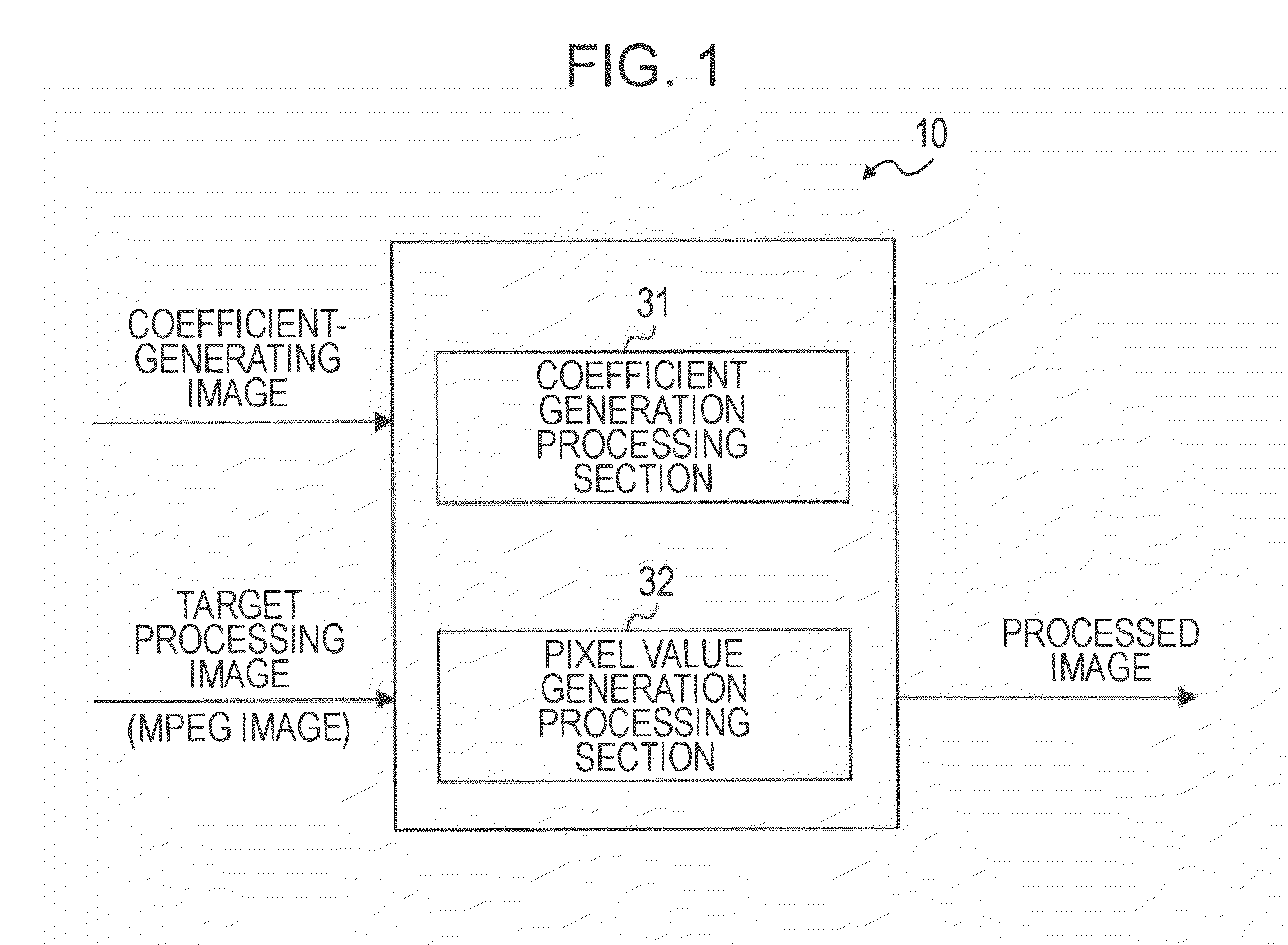
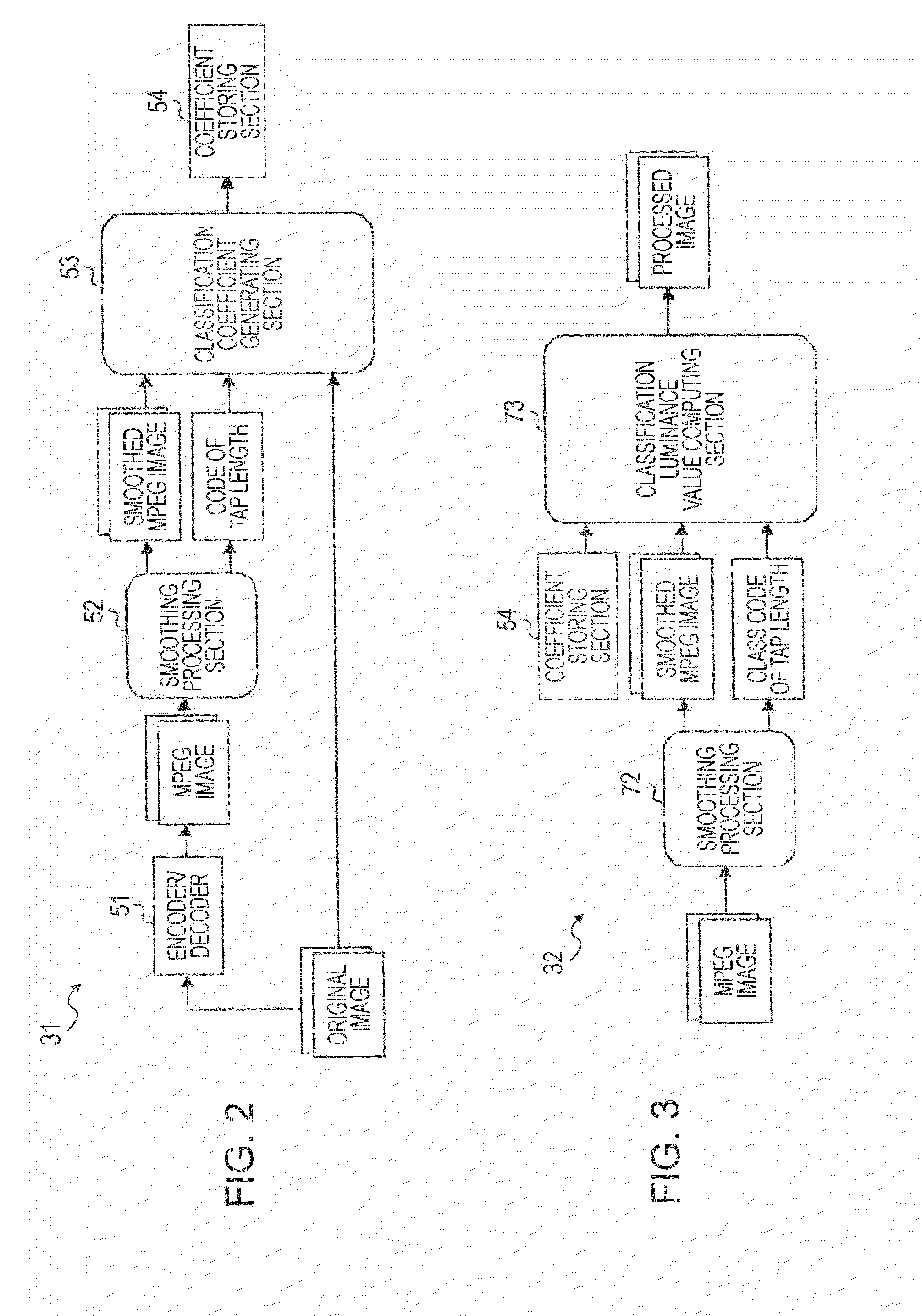
An image processing device includes: a smoothing section configured to extract a smoothing tap and smooth a target image on the basis of pixel values within the tap, the smoothing tap being of variable size and including plural pixels centered on each target pixel of the image; a class tap extracting section configured to extract a class tap including plural pixels centered on each target pixel in the smoothed image; a class code determining section configured to generate a code corresponding to a characteristic of variation of pixel values within the class tap, and determine a class code including a size of the smoothing tap and the code; and a pixel value computing section configured to read tap coefficients corresponding to the determined class code, and multiply pixel values forming a prediction tap extracted from the smoothed image, by the tap coefficients to calculate pixel values of a processed image.

Description

CROSS REFERENCES TO RELATED APPLICATIONS[0001]The present invention contains subject matter related to Japanese Patent Application JP 2007-330092 filed in the Japanese Patent Office on December 21, 2007, the entire contents of which are incorporated herein by reference.BACKGROUND OF THE INVENTION[0002]1. Field of the Invention[0003]The present invention relates to an image processing device and method, a learning device and method, a program, and a recording medium. More specifically, the present invention relates to an image processing device and method, a learning device and method, a program, and a recording medium which make it possible to generate an image with high perceived resolution while reducing perceived noise.[0004]2. Description of the Related Art[0005]For transmission, accumulation, or the like of image data, a compression / encoding process based on JPEG, MPEG, H264 / AVC or the like is frequently employed. For example, in the discrete cosine transform used in MPEG or JP...

Claims


Application Information

Patent Timeline
Patent Type & Authority Applications(United States)
IPC IPC(8): G06K9/40H04N7/12G06K9/62G06K9/46H04N19/00G06V10/30H04N7/01H04N19/117H04N19/136H04N19/176H04N19/189H04N19/196H04N19/44H04N19/86H04N19/98
CPCG06K9/40G06T5/002G06T5/20G06T2207/20081G06T2207/20192H04N19/46H04N19/98H04N19/117H04N19/14H04N19/182H04N19/80H04N19/86H04N19/61G06V10/30
Inventor CHOKI, YUTAKONDO, TETSUJIRO
Owner SONY CORP
Why Eureka
Try Eureka