Box-type motor-operated microscope
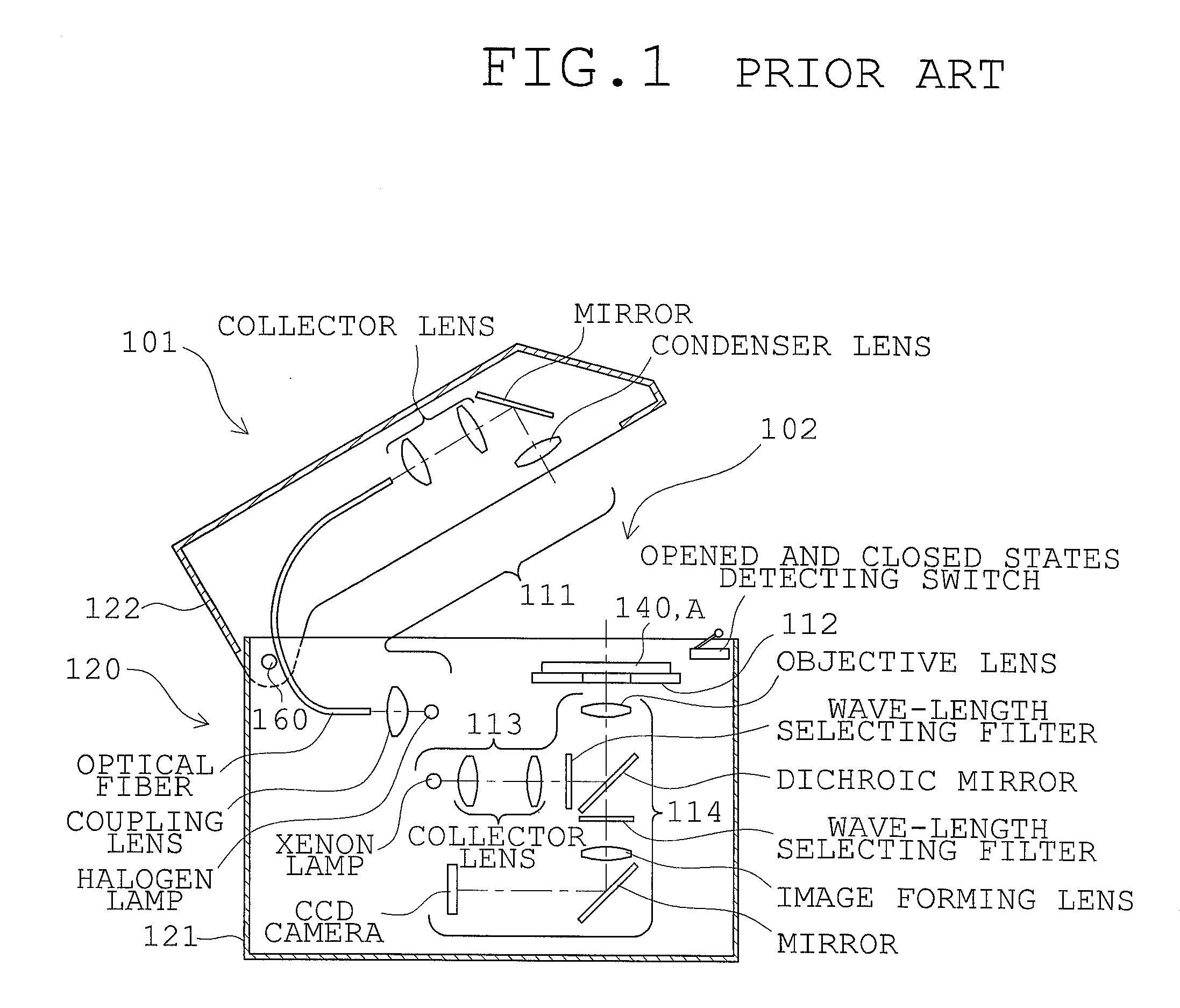
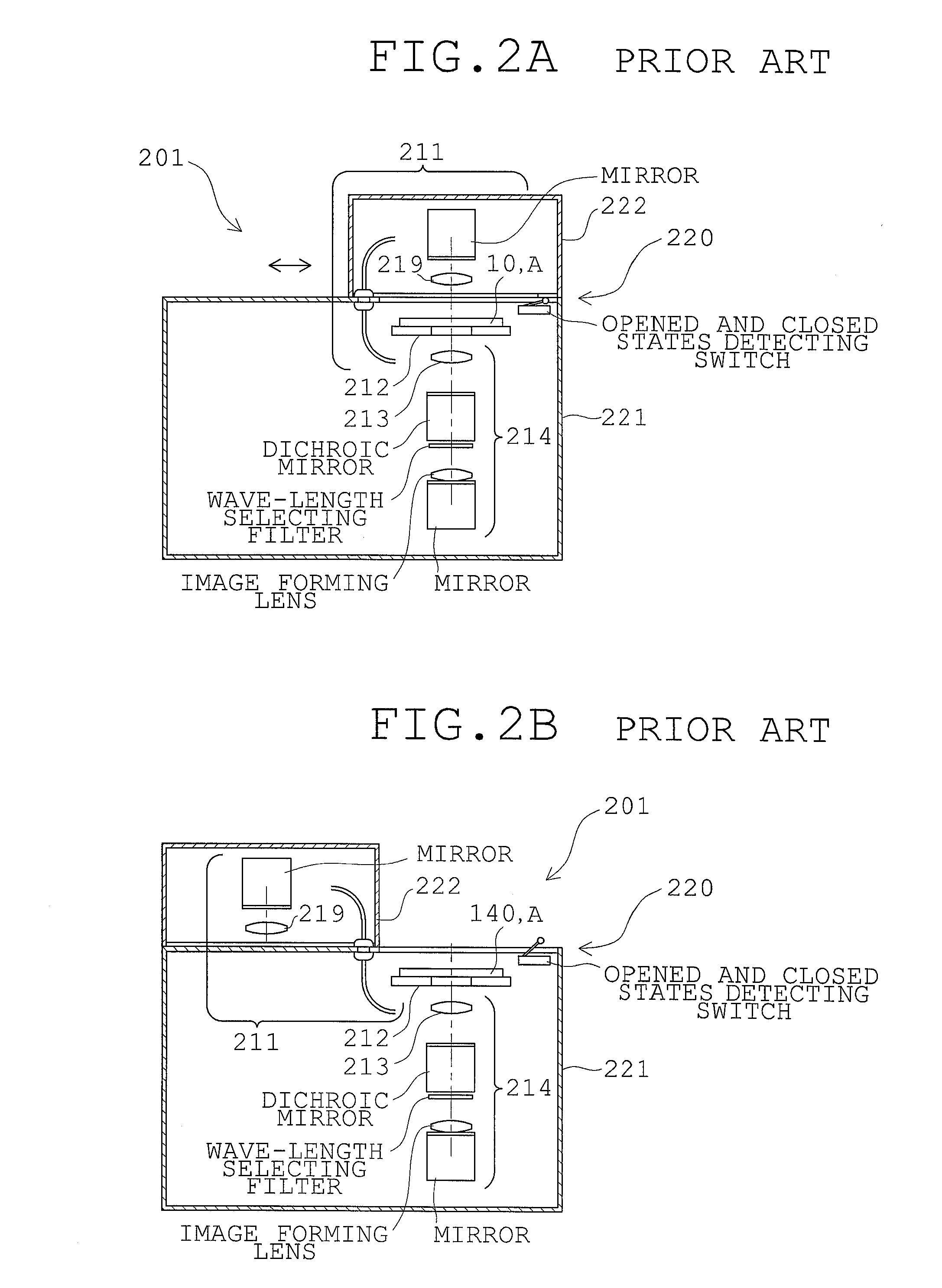
a motor-operated microscope and box-type technology, applied in the field of box-type motor-operated microscopes, to achieve the effect of facilitating the change of observation and/or measurement conditions according to the application, high degree of accuracy, and excellent maneuverability and safety
- Summary
- Abstract
- Description
- Claims
- Application Information
AI Technical Summary
Benefits of technology
Problems solved by technology
Method used
Image
Examples
first embodiment
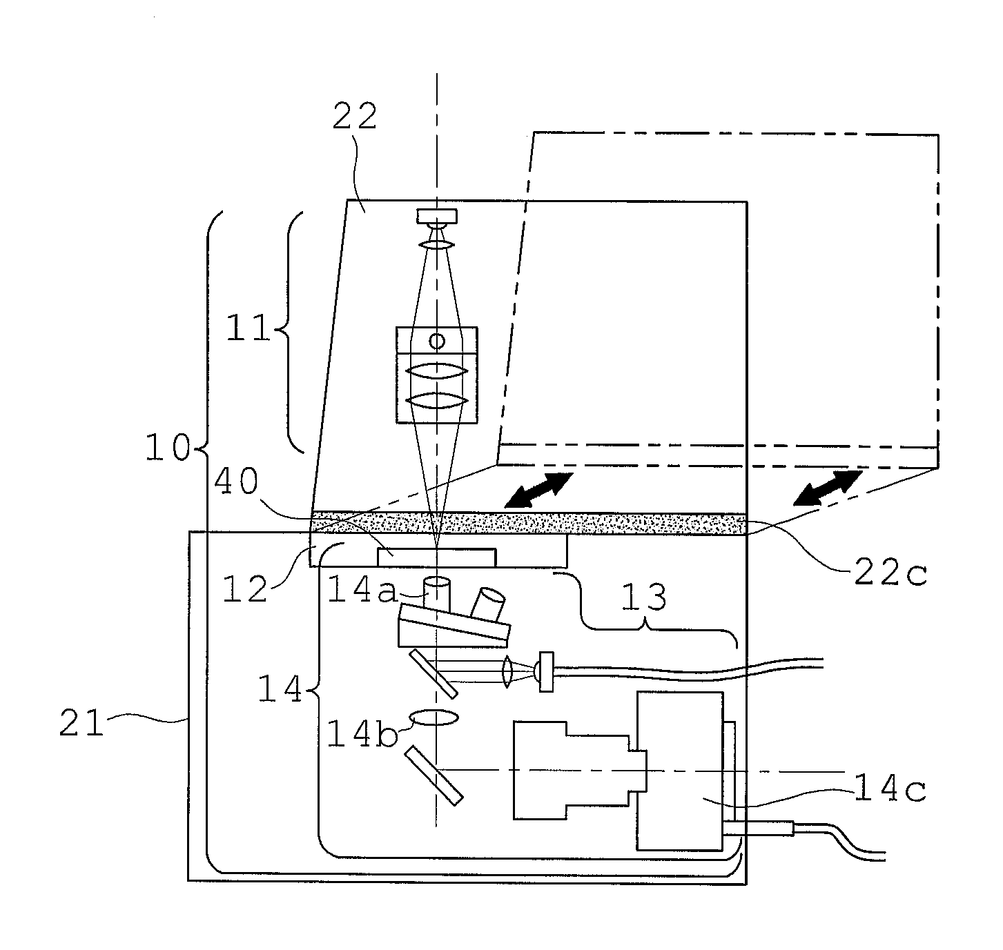
[0052]FIGS. 3A and 3B are explanatory views of the box-type motor-operated microscope according to the first embodiment in the present invention, which are a general view looking obliquely from the front, and a side view showing schematically its internal optical arrangement, respectively. FIG. 4 is a view showing the box-type motor-operated microscope of FIGS. 3A and 3B brought to the opened state, looking obliquely from the front. FIGS. 5A and 5B are a side view and a front view, respectively, for explaining the movement mechanism of the moving housing including essential parts in the box-type motor-operated microscope of FIGS. 3A and 3B.
[0053]The box-type motor-operated microscope of the first embodiment includes a motor-operated microscope section 10 and a housing 20 incorporating the motor-operated microscope section 10. The motor-operated microscope section 10 has a transmitting illumination optical system 11, an electric stage 12, a reflecting illumination optical system 13, ...
second embodiment
[0070]FIGS. 6A, 6B, 6C, and 6D are explanatory views showing structures of essential parts of the box-type motor-operated microscope according to the second embodiment in the present invention, which are a perspective view looking obliquely from the right side back, a rear view, a left-side view, and a sectional view taken along line A-A in FIG. 6C, respectively. FIG. 7 is a sectional view taken along the optical axis of the box-type motor-operated microscope shown in FIG. 6C. Also, like reference numerals are used for like optical members with respect to the structure substantial to the box-type motor-operated microscope of the first embodiment and their specific explanation is omitted.
[0071]In the box-type motor-operated microscope of the second embodiment, besides the structure of the box-type motor-operated microscope of the first embodiment, the fixed housing 21 includes a first fixed housing section 21, and a second fixed housing section 212 provided below the first fixed hous...
third embodiment
[0077]FIG. 8 is an explanatory view chiefly showing the structure of the moving housing constituting essential parts of the box-type motor-operated microscope according to the third embodiment in the present invention. FIG. 9 is an explanatory view showing a state where a reagent is poured, from a pipette, on the specimen in the specimen vessel through an opening and closing window in the box-type motor-operated microscope of FIG. 8.
[0078]In the box-type motor-operated microscope of the third embodiment, the moving housing 22 has opening sections 22d through which the position of the specimen vessel 40 on the optical axis of the objective lens and surroundings thereof can be recognized with the naked eye from outside the moving housing 22 in a state where the moving housing 22 abuts on the fixed housing 21, and opening and closing doors 22e opening and closing the opening sections 22d at three places of the front and both sides of the moving housing 22. Also, the opening section 22d...
PUM
 Abstract
Description
Claims
Application Information
 - R&D
- Intellectual Property
- Life Sciences
- Materials
- Tech Scout
- Unparalleled Data Quality
- Higher Quality Content
- 60% Fewer Hallucinations
Browse by: Latest US Patents, China's latest patents, Technical Efficacy Thesaurus, Application Domain, Technology Topic, Popular Technical Reports.
© 2025 PatSnap. All rights reserved.Legal|Privacy policy|Modern Slavery Act Transparency Statement|Sitemap|About US| Contact US: help@patsnap.com


