
Interrupt morphing and configuration, circuits, systems, and processes

a technology of interrupt morphing and configuration, applied in the field of electronic computing hardware and software and communications, can solve problems such as insufficient security and may or may not provide privacy

Active Publication Date: 2009-06-18
TEXAS INSTR INC
View PDF35 Cites 189 Cited by
  • Summary
  • Abstract
  • Description
  • Claims
  • Application Information

AI Technical Summary

Benefits of technology

[0013]Generally and in one form of the invention, an electronic configuration circuit includes a processing circuit operable for executing instructions and responsive to interrupt requests and operable in a plurality of execution environments selectively wherein the execution environment is activated or suspended, a first configuration register coupled to the processing circuit for identifying the interrupt r...

Problems solved by technology

However, the higher level of privilege may or may not provide adequate security for m-commerce and e-commerce, given that this higher level relies on proper operation of operating systems.

Method used


Image

  • Interrupt morphing and configuration, circuits, systems, and processes
  • Interrupt morphing and configuration, circuits, systems, and processes
  • Interrupt morphing and configuration, circuits, systems, and processes

Examples


first embodiment

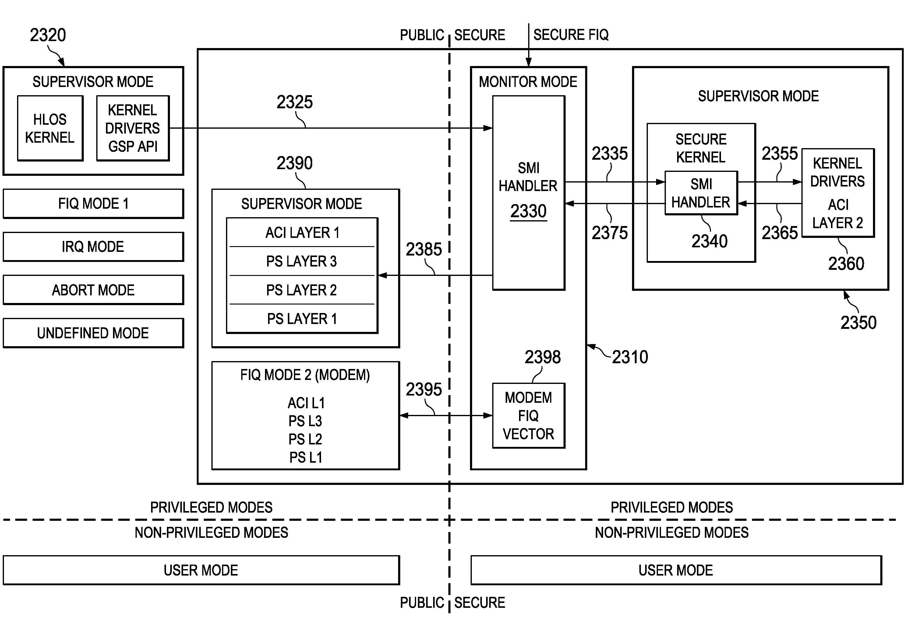
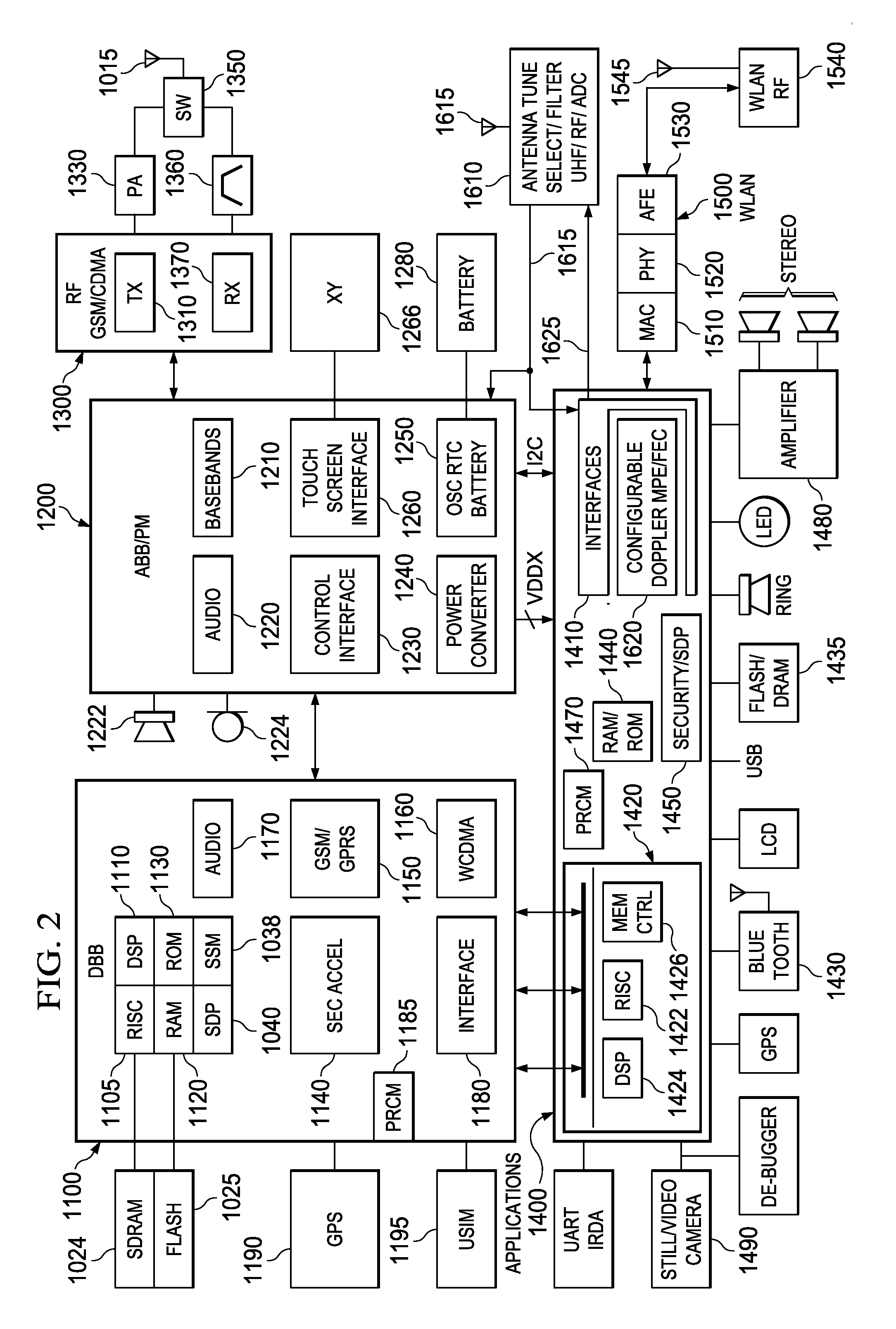
[0129]A first embodiment has an application engine including a RISC core, system DMA, and dedicated peripherals. Coupled to the application engine is a Modem engine including a DSP plus modem DMA plus dedicated peripherals. Shared memory such as SDRAM and Flash memory and shared peripherals such as USB serial bus are coupled to both the application engine and the modem engine.

[0130]A second embodiment is similar to the first embodiment except that the modem engine is virtualized onto the RISC core and uses the same system DMA, but has modem-dedicated peripherals. The second embodiment has the modem engine run on the same core MPU 2610 with a modem RTOS using the same system DMA and co-existing with a Public HLOS. To deal with the constraints of the second embodiment, recreation of the two distinct engines (application and modem) is accomplished by effectively virtualizing the distinct engines onto the RISC core and system DMA. They are transformed into categories in FIG. 4.

[0131]The...

embodiment 5000

[0479]In FIGS. 22A and 22B, a four-CPU hardware-supported hypervisor embodiment 5000 of FIGS. 21A / 21B / 21C is shown in more detail. FIGS. 22A / 22B can be compared with and supplemented by the embodiments shown in FIGS. 26A / 26B and FIGS. 6 / 6A, 9A / 9B, 10, 11, 12 / A / B, 13, 21A / B / C and other description elsewhere herein. EEs, Hypervisor and Secure Kernel run in the system coherently. MMUi (Memory Management Units) for each of the CPUi (CPU0-3), L1$i (Level 1 Cache) for each of the CPUi (CPU0-3), and a shared Snoop Control Unit SCU 5010 are provided for memory management and cache coherency to the extent desired. Public Virtual OS or RTOS (WinCE, Nucleus, etc.) runs non-coherently and as a not-shared device with an MMU.

[0480]In FIG. 22A, a Generalized Interrupt Handler GIC 5020 handles interrupts that are selectively masked and routed to respective GIC Bus 0-3 ports corresponding to each of the CPU cores CPU0-3 and operates in combination with structures as described in connection with FIGS...


PUM


Abstract

An electronic configuration circuit includes a processing circuit (2610) operable for executing instructions and responsive to interrupt requests and operable in a plurality of execution environments (EE) selectively wherein a said execution environment (EE) is activated or suspended, a first configuration register (SCR) coupled to the processing circuit (2610) for identifying the interrupt request as an ordinary interrupt request IRQ when the execution environment (EE) is activated (EE_Active); and a second configuration register (SSM_FIQ_EE_y) for associating an identification of that execution environment (EE) with the same interrupt request, the processing circuit (2610) coupled (5910) to the second configuration register (SSM_FIQ_EE_y) to respond to the same interrupt request as a more urgent type of interrupt request when that execution environment (EE) is suspended (5920).

Description

CROSS-REFERENCE TO RELATED APPLICATIONS[0001]This application is related to “Hypervisor Instantaneous Interrupt Dispensation” TI-65042 EP PS European patent application No. 07291519.2 / EP07291519 filed 13.12.07 (Dec. 13, 2007), and Paris Convention priority is claimed under 35 U.S.C. 119 and / or all other applicable law.[0002]This application is related to “Interrupt-Related Circuits, Systems, and Processes,” TI-63816 / 65042 EP PS European patent application No. 08290292.5 EP filed Mar. 27, 2008, and Paris Convention priority is claimed under 35 U.S.C. 119 and / or all other applicable law.STATEMENT REGARDING FEDERALLY SPONSORED RESEARCH OR DEVELOPMENT[0003]Not applicable.COPYRIGHT NOTIFICATION[0004]Portions of this patent application contain materials that are subject to copyright protection. The copyright owner has no objection to the facsimile reproduction by anyone of the patent document, or the patent disclosure, as it appears in the United States Patent and Trademark Office, but ot...

Claims


Application Information

Patent Timeline
IPC IPC(8): G06F13/24G06F1/08
CPCG06F1/3203G06F1/324G06F1/3296Y02B60/144G06F21/74Y02B60/1217Y02B60/1285G06F9/4812Y02D10/00
Inventor GOSS, STEVENCONTI, GREGORY
Owner TEXAS INSTR INC
Learn More