
Method and system for data synchronization, and apparatus thereof

a data synchronization and data technology, applied in the field of data processing technologies in networks, can solve the problems of inability to tell which data item has been synchronized and which data item still needs to be synchronized, and the guid mapping table in the server becomes useless, and achieves the effect of reducing the quantity of data, short data characteristic information, and improving data synchronization efficiency

Active Publication Date: 2009-06-18
HUAWEI TECH CO LTD
View PDF12 Cites 97 Cited by
  • Summary
  • Abstract
  • Description
  • Claims
  • Application Information

AI Technical Summary

Benefits of technology

[0031]The present disclosure provides a data synchronization method to decrease data transmission quantity and increase data synchronization efficiency.
[0032]The present disclosure also provides a data synchronization system to decrease data transmission quantity and increase data synchronization efficiency.
[0033]And the present disclosure also provides data synchronization apparatus to decrease data transmission quantity and increase data synchronization efficiency.
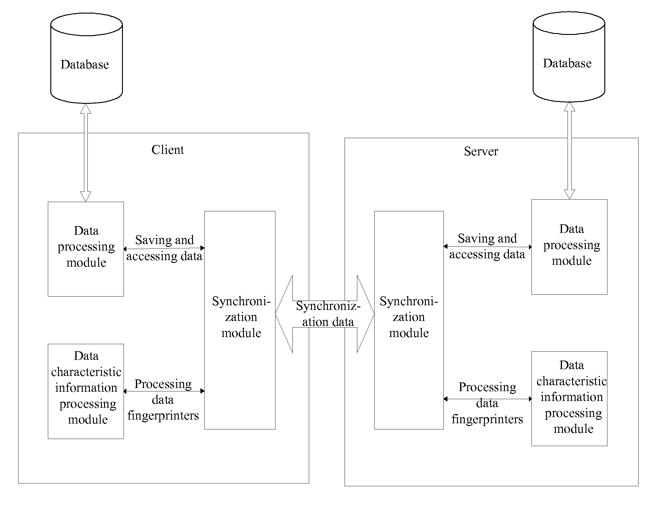
[0043]the synchronization module is configured to compare the data characteristics of the data sent from a server with the data characteristics set up by the data characteristic information processing module for corresponding data, send a result of the comparison to the server, receive the data synchronization message carrying the synchronization data from the server, and forward the data synchronization message to the data processing module; or the synchronization module is configured to send the data characteristic set up by the data characteristic information processing module to the server, receive the result of the comparison from the server, and send data synchronization message carrying synchronization data to the server according to the result of the comparison so that the server can synchronize the data on the server.
[0048]According to the above-mentioned method, system and apparatus, data characteristic information for the data stored in the client database and in the server database is set up respectively. To be specific, the data characteristic of the data in the client database is set up by the client by computing, and the data characteristic of the data in the server database is set up by the server by computing or received by the server from the client and stored by the server. When the client and the server synchronize data thereof, the client sends to the server the data characteristic set up for the data in the client database. The server verifies the data characteristic of corresponding data stored in the server database based on the received data characteristic, and sends to the client the information about the data failing to pass verification. The client begins to synchronize the data failing to pass verification according to the information received from the server. The length of the data characteristic information is short comparatively, therefore the data to be transmitted by the client sending the data characteristic information to the server for verification, are much less than the data transmitted by the client having to send all the data in the client database to the server. Even the quantity of the data characteristic information and the data to be synchronized after the verification, i.e., the data failing to the pass the verification, is less than the quantity of all data in the client database. Hence the system, method and apparatus provided by the present disclosure reduce the quantity of data to be transmitted in the data synchronization process, store the network bandwidth and improve the data synchronization efficiency.

Problems solved by technology

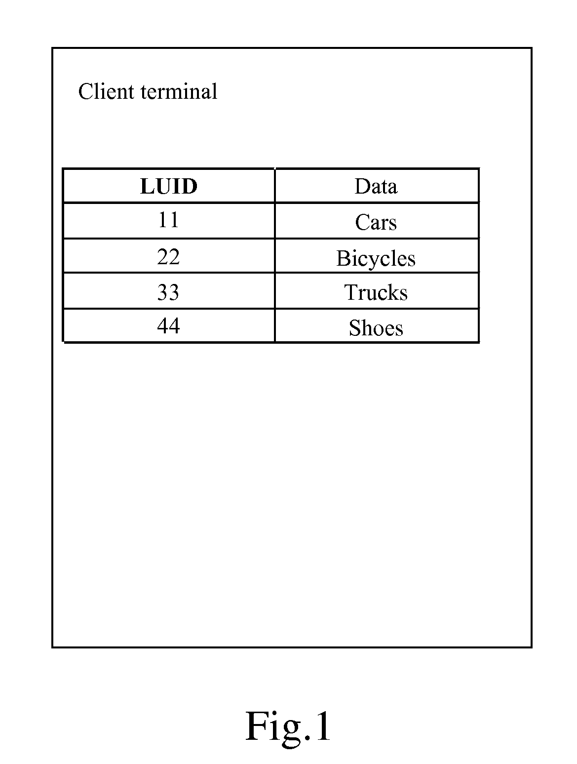
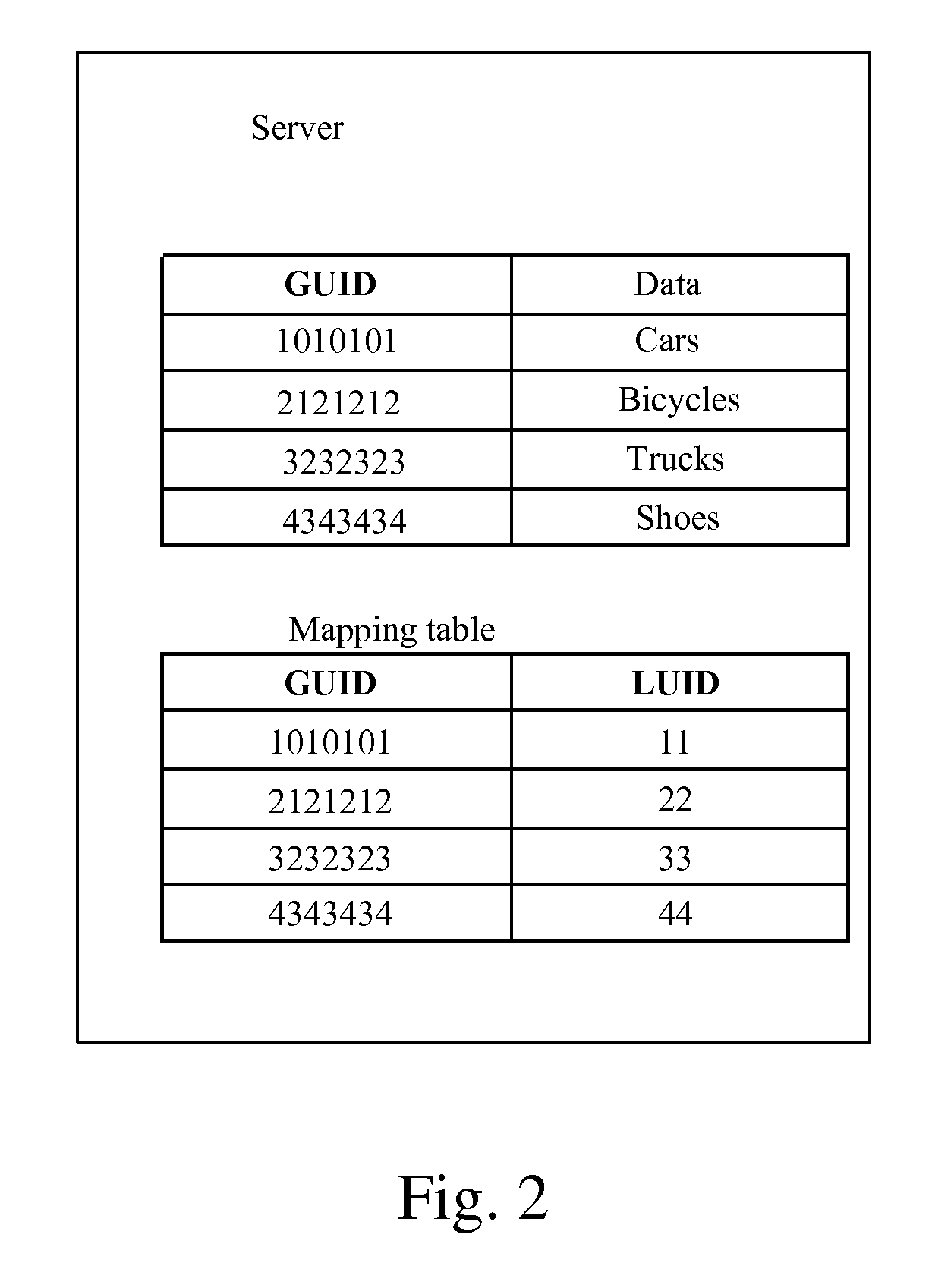
The first reason is that the LUIDs in the client database are out of order or lost, the re-use of LUID by the client or the re-creature of LUID would make the LUIDs out of order, thus the LUID-GUID mapping table in the server becomes useless, and the client and the server are unable to determine how data items in databases correspond to each other.
The second reason is that the Change Log in the client database is lost, so it becomes impossible to tell which data item has been synchronized and which data item still needs to be synchronized.

Method used


Image

  • Method and system for data synchronization, and apparatus thereof
  • Method and system for data synchronization, and apparatus thereof
  • Method and system for data synchronization, and apparatus thereof

Examples


embodiment 1

[0226 is described as follows, which is an embodiment of the present disclosure in the first situation shown in Table 4.

[0227]At first, initial states of the data items in the client database and in the server database are shown in FIG. 8a.

[0228]After a period of time, the data items in client database and the server database are modified as shown in FIG. 8b.

[0229]Next, the Change Log of the data items in the client database is lost, as shown in FIG. 8c.

[0230]At last, the data fingerprints are compared.

[0231]Step A: The client detects that the Change Log of the data items in the client database is lost. In initial stage of the data synchronization, the client sends the server a request for initiating smart sync with a reason value indicating that Change Log is lost.

[0232]Step B: The server returns a smart sync confirmation message.

[0233]Step C: The client sends the server the LUID-fingerprints of the data items in the client database, the LUID-fingerprints include {}.

[0234]Step D...

embodiment 2

[0242 is described as follows, which is an embodiment of the present disclosure in the second situation shown in Table 4.

[0243]At first, all LUIDs of the data items in the client database are invalidated. And on the server, a mapping between the LUIDs and the GUIDs is invalidated too. In such situation, the client will assign new LUIDs to the data items in the client database. The objective of the smart sync in such situation is to re-establish the GUID-LUID mapping on the server in a fast and efficient way, and synchronize the data items in the client database with corresponding data items in the server database.

[0244]Next, as shown in FIG. 9a, the client assigns new LUIDs to the data items in the client database. The corresponding relations stored in the server database are invalidated, so matching data items can only be found based on the data fingerprints, and data items without matching data fingerprints are regarded as new items.

[0245]At last, the data fingerprints in the two ...

embodiment 3

[0253 is described as follows, which is an embodiment of the present disclosure in the first situation shown in Table 4.

[0254]At first, the initial states of the data items in the client database and in the server database are shown in FIG. 10a. Then the data items in client database and the server database are modified as shown in FIG. 10b.

[0255]Next, the Change Log of the data items in the client database is lost, as shown in FIG. 10c.

[0256]At last, the data fingerprints in the two databases are compared.

[0257]Step A: The client detects that the Change Log of the data items in the client database is lost. In the initial stage of the data synchronization, the client sends a request for initiating smart sync with a reason value indicating that Change Log is lost.

[0258]Step B: The server returns a smart sync confirmation message.

[0259]Step C: The client sends the server the LUID-fingerprints of the data items in the client database, the LUID-fingerprints are as follows: {}.

[0260]St...


PUM


Abstract

Embodiments of the present disclosure disclose a data synchronization method, system and apparatuses thereof. The data synchronization method includes the following processes: sending, by a client, a data characteristic verification message carrying one or multiple data characteristics for data in a client database, to a server; comparing, by the server, the one or multiple data characteristics carried in the data characteristic verification message with the data characteristics for the data in a server database; determining, by the server, the data to be synchronized based on a result of the comparing and sending the client a data characteristic verification response carrying information indicating the determined data to be synchronized; and determining, by the client, the data to be synchronized according to the information in the data characteristic verification response, and synchronizing the determined data to be synchronized with the server. The method, system and apparatus thereof provided by the embodiments of the present disclosure can reduce the amount of data to be transmitted in data synchronization, and improve the efficiency of data synchronization.

Description

[0001]This application is a continuation of PCT / CN2007 / 000284, filed Jan. 25, 2007, which in turn claims priority from Chinese patent application No. 200610003042.6 filed with the Chinese Patent Office on Jan. 26, 2006, and from Chinese patent application No. 200610085153.6 filed with the Chinese Patent Office on May 31, 2006, all of which are incorporated herein by reference in their entirety.FIELD OF THE INVENTION[0002]The present invention relates to data processing technologies in networks, and particularly, to method and system for data synchronization, and apparatus thereof.BACKGROUND OF THE INVENTION[0003]In February, 2000, SyncML initiative was created to synchronize personal information or corporation data between multiple platforms and networks. The objective of creating the SyncML initiative was to make a user, a device manufacturer, a basic component developer, a data provider, an application developer and a service provider cooperate with each other, and enable network ...

Claims


Application Information

Patent Timeline
IPC IPC(8): G06F15/16G06F17/30
CPCH04L67/1095G06F17/30581G06F16/275
Inventor KANG, JIAOGUO, XIANGZHOUTIAN, LINYI
Owner HUAWEI TECH CO LTD
Learn More