
Enhanced surface-emitting photonic device

a photonic device and enhanced technology, applied in the direction of lasers, optical resonator shape and construction, semiconductor lasers, etc., can solve the problems of relatively large devices, spatial separation of the feedback region from the gain region, and the provision of lasing mode at the edges of the devices, so as to enhance the performance of the feedback region

Active Publication Date: 2009-06-11
GLOBALFOUNDRIES US INC
View PDF6 Cites 16 Cited by
  • Summary
  • Abstract
  • Description
  • Claims
  • Application Information

AI Technical Summary

Benefits of technology

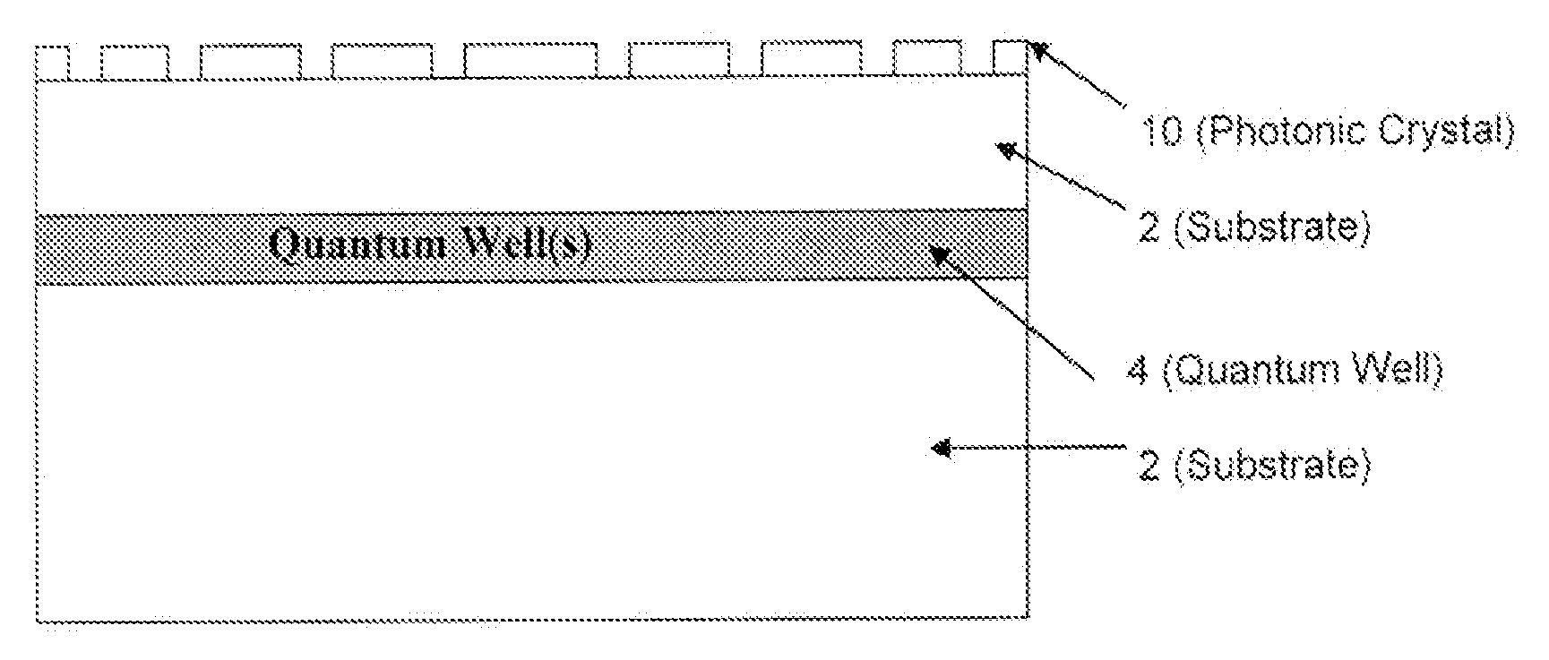
[0007]In accordance with an embodiment of the invention, a surface-emitting photonic device is provided and comprises a structure disposed therein to enhance a performance thereof, the structure including a two dimensionally periodic second order distributed feedback device (DFB) to emit diffraction limited outcoupled laser light having a predetermined wavelength along a propagation direction that is substantially normal to a plane of the DFB, and a first order distributed Bragg reflector (DBR) coplanar with, adjacent to and surrounding the DFB, a geometry of the DBR being selected such that a bandgap of the DBR is maximized and centered around the predetermined wavelength of the emitted light, a substrate on which the structure is patterned, and either an optical gain layer, disposed above the substrate and the structure, or a semi-conductor quantum well laser disposed within the substrate.

Problems solved by technology

An important drawback of DBRs, however, is that a feedback region thereof is spatially separated from the gain region.
As a result, the devices are relatively large.
The main drawback of DFB, however, is that the lasing mode is provided at edges of the devices where the corresponding laser exits a resonator as a loss.
The presence of this loss in these devices leads to a high lasing threshold thereof.
An important drawback of linear gratings, however, is that the laser light is outcoupled in a fan-like manner, which may not be beneficial for most applications (e.g., fiber coupling).

Method used


Image

  • Enhanced surface-emitting photonic device
  • Enhanced surface-emitting photonic device
  • Enhanced surface-emitting photonic device

Examples


Embodiment Construction

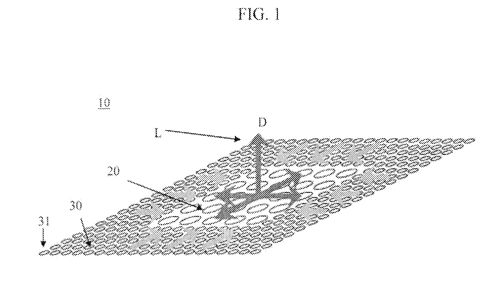
[0015]With reference to FIGS. 1, 4 and 5, an enhanced surface emitting photonic device 1, as shown in FIGS. 4 and 5, includes a photonic crystal as a distributed feedback / distributed Bragg reflector (hereinafter referred to as a “DFB / DBR”) structure 10. An exemplary embodiment of the DFB / DBR structure 10 is illustrated schematically and not to scale in FIG. 1. As shown, the DFB / DBR structure 10 includes a two dimensionally periodic second order distributed feedback device (DFB) 20 surrounded by a first order distributed Bragg reflector (DBR) 30. As such, the DFB / DBR structure 10 provides for diffraction limited outcoupled emitted laser light, L, having a propagation direction (see arrow D) that is substantially normal to a plane of the structure 10.

[0016]With reference to FIGS. 1, 2 and 3, according to embodiments of the invention, the DFB / DBR structure 10 comprises the two dimensionally periodic second order distributed feedback device (DFB) 20 that acts, in this case, as a laser r...


PUM


Abstract

A surface-emitting photonic device including a structure disposed therein to enhance a performance thereof. The structure includes a two dimensionally periodic second order distributed feedback device (DFB) to emit diffraction limited outcoupled laser light having a predetermined wavelength along a propagation direction that is substantially normal to a plane of the DFB, and a first order distributed Bragg reflector (DBR) coplanar with, adjacent to and surrounding the DFB, a geometry of the DBR being selected such that a bandgap of the DBR is maximized and centered around the predetermined wavelength of the emitted light, a substrate, and either an optical gain layer, or a semi-conductor quantum well laser disposed within the substrate.

Description

BACKGROUND OF THE INVENTION[0001]1. Field of the Invention[0002]Aspects of the present invention relate to ail enhanced surface-emitting photonic device and, more particularly, to an enhanced surface-emitting photonic device including a structure disposed therein to enhance a performance thereof.[0003]2. Description of the Background[0004]Conventional compact and low-threshold lasers play an important role for pushing integrated optics towards series-production readiness and generally incorporate distributed Bragg reflectors (DBRs). An important drawback of DBRs, however, is that a feedback region thereof is spatially separated from the gain region. As a result, the devices are relatively large.[0005]Another approach in conventional lasers is the use of distributed feedback (DFB) structures. Here, the gain region is incorporated into the feedback region. The main drawback of DFB, however, is that the lasing mode is provided at edges of the devices where the corresponding laser exits...

Claims


Application Information

Patent Timeline
IPC IPC(8): H01S3/06H01S3/07H01S5/185H01S5/12
CPCH01S5/105H01S5/18H01S5/125H01S5/12H01S5/11H01S5/187H01S5/185
Inventor BAUMANN, KRISTIAN GOTTHOLDMAHRT, RAINER FRIEDBERTMOLL, NIKOLAJSTOFERLE, THILO HERMANN
Owner GLOBALFOUNDRIES US INC
Learn More