
Synchronizing wireless local area network access points

a wireless local area network and access point technology, applied in the direction of frequency-division multiplex, synchronisation arrangement, instruments, etc., can solve the problem that the transmission of two access points during the overlap period may have a high probability of colliding, so as to reduce, minimize, or eliminate the overlap

Inactive Publication Date: 2009-06-11
AT&T INTPROP I L P
View PDF10 Cites 73 Cited by
  • Summary
  • Abstract
  • Description
  • Claims
  • Application Information

AI Technical Summary

Benefits of technology

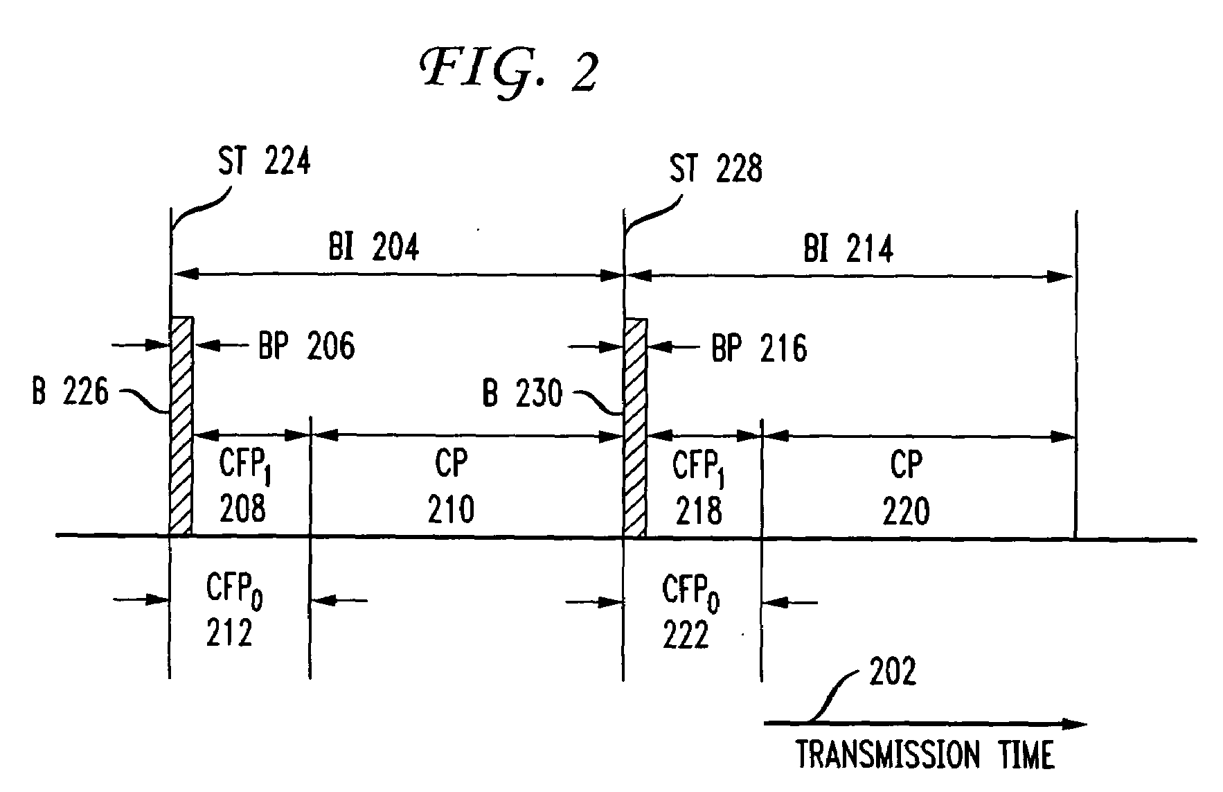
[0015]Embodiments of the invention reduce, minimize, or eliminate the interval in which the two contention-free periods overlap. A monitor station positioned in the area of overlapping RF coverage receives beacon frames from both access points and records the arrival times of the beacon frames. A manager in communication with both access points and the monitor station receives the beacon information reported by the monitor station and calculates a retardation interval for retarding transmission of the beacon frames from the second access point. The retardation interval is calculated to reduce, minimize, or eliminate the overlap between the contention-free period of the second access point and the contention-free period of the first access point. The manager issues a control command to the second access point to retard transmission of its beacon frame by the retardation interval. In embodiments of the invention, the manager may also issue commands to the first and access points to adjust their contention-free periods.

Problems solved by technology

If the contention-free period of the second access point overlaps with the contention-free period of the first access point, transmissions from the two access points during the overlap period may have a high probability of colliding.

Method used


Image

  • Synchronizing wireless local area network access points
  • Synchronizing wireless local area network access points
  • Synchronizing wireless local area network access points

Examples


Embodiment Construction

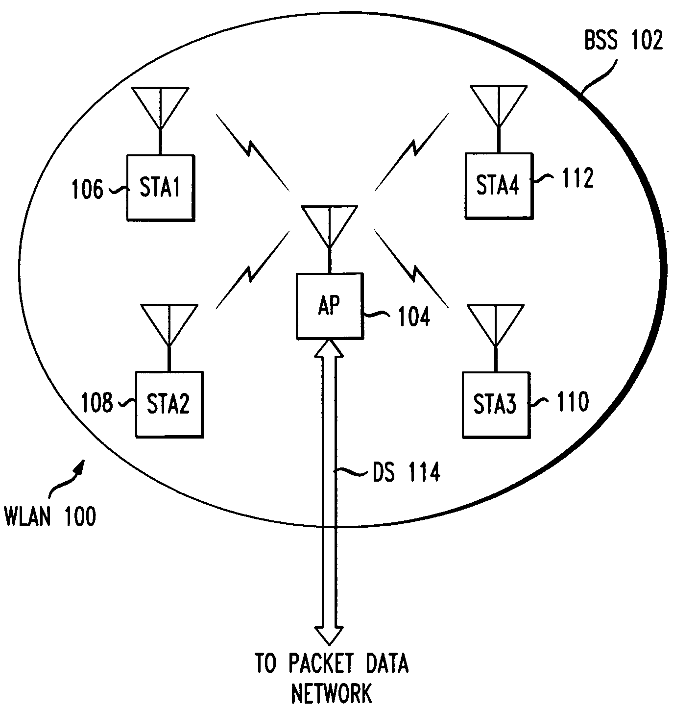
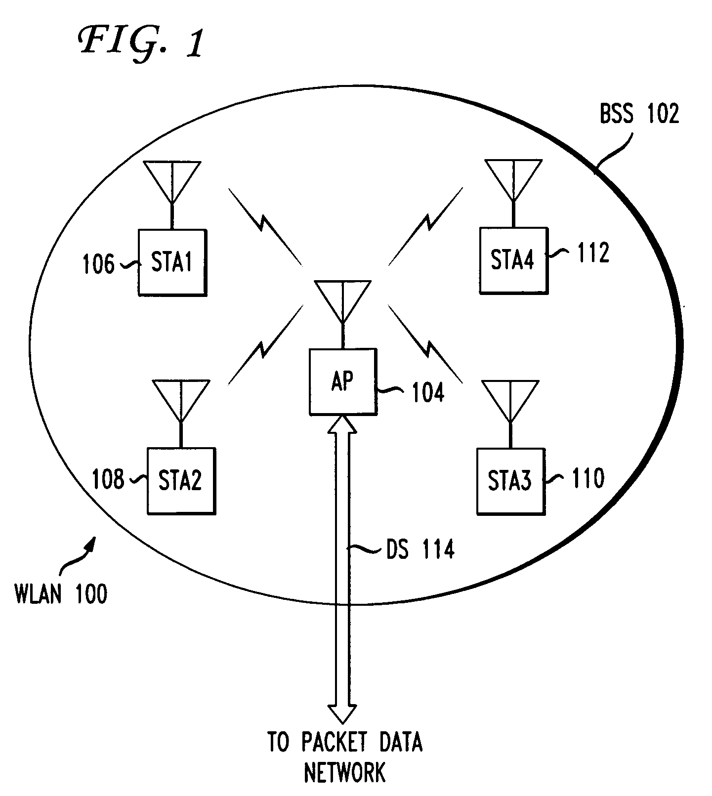
[0026]FIG. 1 shows the basic network architecture of WLAN 100 with a single access point AP 104. The nomenclature of the IEEE 802.11 standards is used herein. In a WLAN, any addressable device may be called a station (STA). Stations may be fixed, portable, or mobile. A portable STA is a device which is capable of being moved from place to place, such as a laptop which may be moved from one desk to another. During operation, however, a portable device is stationary. A mobile STA is a user device, such as a laptop or personal digital assistant, which is in actual motion during operation. In FIG. 1, four stations, STA1106-STA4112, are shown. The stations STA1106-STA4112 communicate over RF links with access point AP 104, which connects via distribution system DS 114 to a packet data network, details of which are not shown. An example of a distribution system is a wired Ethernet local area network (LAN).

[0027]An AP may be considered as a special class of STA. It provides management serv...


PUM


Abstract

In a wireless local area network, a first and second access point in which the RF coverage areas overlap are synchronized by positioning a monitor station within the overlap area. The monitor station receives beacon frames from both access points and records the arrival times. A manager in communication with both access points and the monitor station calculates a retardation interval and issues a control command to the second access point to retard transmission of its beacon frame. The retardation interval is calculated such that the contention-free period of the second access point does not overlap the contention-free period of the first access point. The manager may also issue control commands to the first and second access points to adjust their contention-free periods.

Description

BACKGROUND OF THE INVENTION[0001]The present invention relates generally to wireless local area networks, and more particularly to synchronization of wireless local area network access points.[0002]Popular communications services, such as access to the global Internet, e-mail, and file downloads, are provided via connections to packet data networks. To date, user devices, such as personal computers, have commonly connected to a packet data network via a wired infrastructure. For example, a patch cable connects the Ethernet port on a personal computer to an Ethernet wall jack, which is connected by infrastructure cabling running through the walls of a building to network equipment such as a switch or router. There are disadvantages to a wired infrastructure. From a network perspective, providing packet data services to homes and commercial buildings requires installation of infrastructure cabling. From a user perspective, access to the network is limited to availability of a wall jac...

Claims


Application Information

Patent Timeline
IPC IPC(8): H04J3/06
CPCH04W84/12H04W56/00H04W74/02H04J3/0664H04J3/06H04W74/006
Inventor JI, LUSHENGMILLER, ROBERTWORSTELL, HARRY
Owner AT&T INTPROP I L P
Learn More