
Rear projection immersive display system

a display system and projection system technology, applied in the field of projection systems, can solve the problems of large and cumbersome, prohibitively expensive for many uses, and the front projection method is not well suited to single-user and other small-scale systems, and achieve the effect of efficient transfer

Inactive Publication Date: 2009-06-04
KROLL WILLIAM STEVEN
View PDF0 Cites 6 Cited by
  • Summary
  • Abstract
  • Description
  • Claims
  • Application Information

AI Technical Summary

Benefits of technology

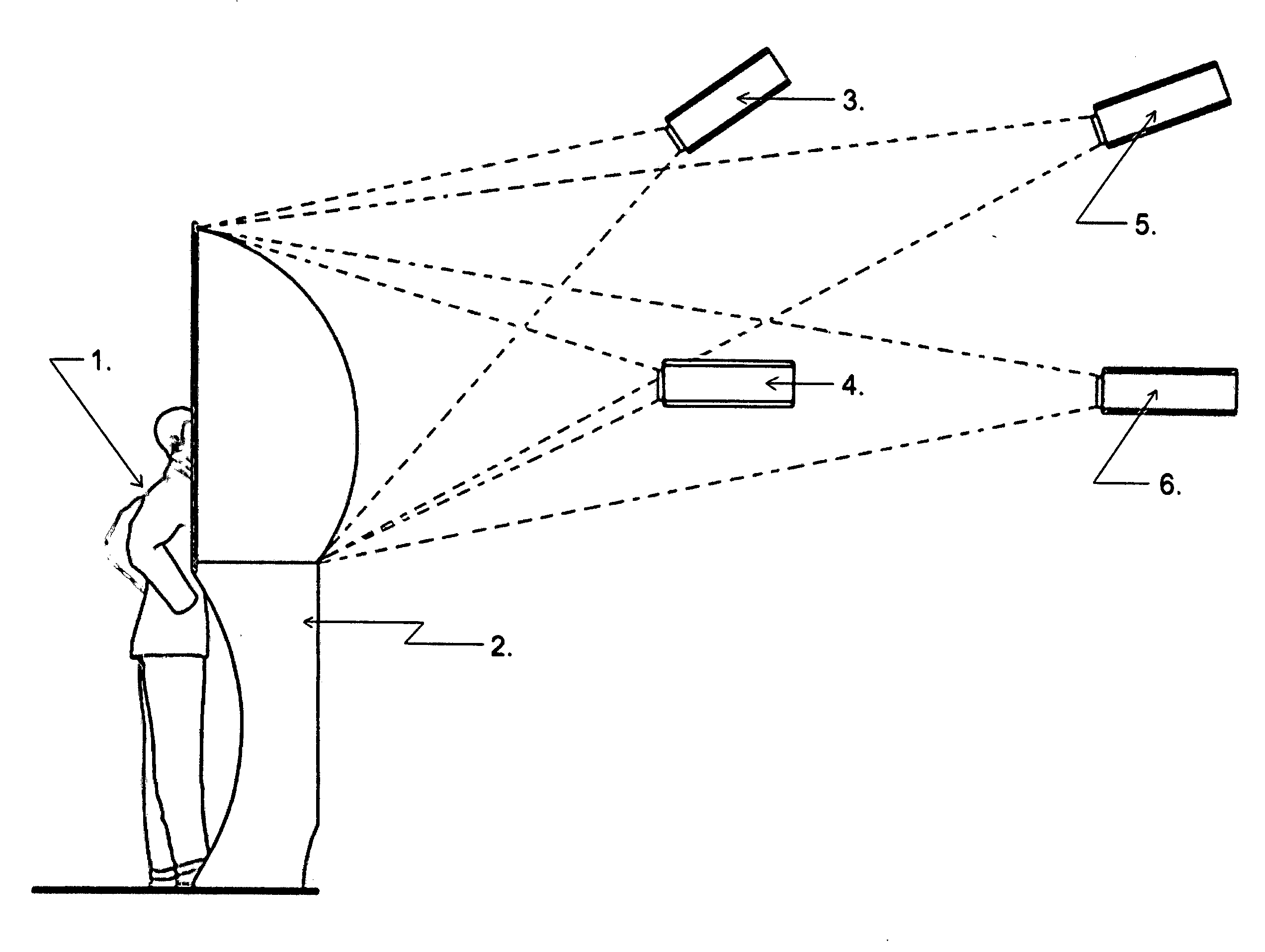
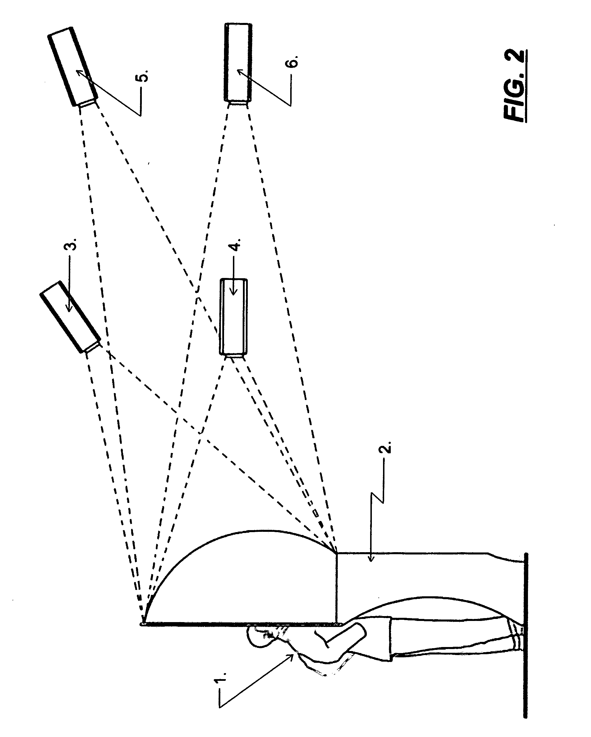
[0009]According to other embodiments of the present invention an immersive rear-projection display system according to the present invention are adapted for use by a viewer and include a dome. Said dome having a vertically oriented open front end with a light shaping diffuser on its exterior (convex) surface and a touch screen display situated within said dome space structure visual presentation system for use by a viewer includes a dome having an open front end and a truncated lower quadrant section thus allowing the viewer to physically enter the dome structure for an effective immersive viewing experience. A projector is located outside the dome to project a geometrically corrected concave image onto the convex outer dome surface. An interactive touch screen display is provided to the viewer to control the environment, including but not limited to, interaction with the projection dome image, the interior secondary display and the audio system.
[0010]The transparent dome acts as a lens, its geometry effectively bending the incoming light of the projection system inwards towards the viewer. A plurality of randomized micro-articulated structures on its convex outer surface render it as an effective light shaping diffuser. These randomized micro-articulated surface features on the convex exterior of the dome provide an effective means of capturing the projector's image from a wide possible range of angles and efficiently transferring them onto the primary interior (concave) viewing surface of the dome.

Problems solved by technology

However, such systems may be large and cumbersome and often cost several hundreds of thousands of dollars, thus making them prohibitively expensive for many uses.
The front projection method is not well suited to single-user and other small-scale systems because they typically locate the projection apparatus, or a part thereof, in the same ideal area in which we desire to place the viewer.

Method used


Image

  • Rear projection immersive display system
  • Rear projection immersive display system
  • Rear projection immersive display system

Examples


Embodiment Construction

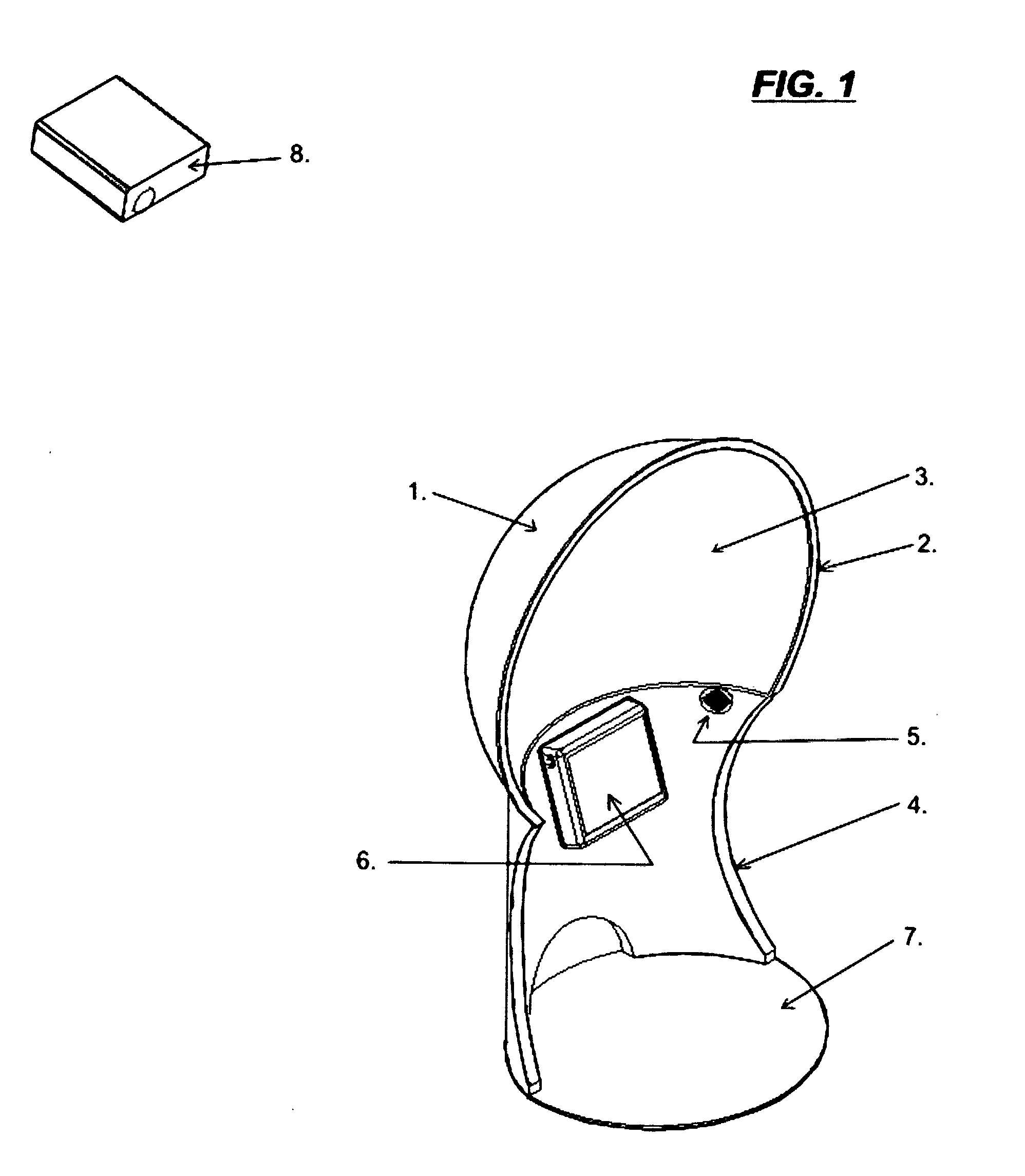
[0041]Referring to FIG. 1, a preferred embodiment of the rear projection immersive display system described herein, indicated generally at reference numeral 1 is the truncated dome. Said truncated dome being primarily spherical in geometry. It is formed from a material having a high index of refraction.

[0042]Said high index of refraction being above the refractive index of the air which surrounds it. Said material may be, though not limited to, polymethyl methacrylate, commonly referenced by the trade name of acrylic, polyacrylate, or of a glass of any known nature. The high index of refraction being desirable in this application as it enhances the viewability of the image formed on the surface of the truncated dome screen.

[0043]In the embodiment illustrated, said dome shaped screen has its front edge finished with a flange (2), the dimension of which may be of a width relative to the thickness of the material being utilized, this being especially desirable when the dome is formed f...


PUM


Abstract

An immersive rear projection imaging and audio system with interactive capability. It utilizies a single projection device. Said device receiving its image correction information via a computer interface. The computer interface is performing 3-D geometric image reformation and correction from the source. Said source may be supplied by any commercially available media or means. The receiving surface of the specially treated, vertically oriented open ended dome screen having a truncated lower quadrant section. Within said hemispherical display screen, the viewer's field of vision is immersed within the projected image. We further cause an immersive audio experience within this same space and present a method for producing same.

Description

BACKGROUND OF THE INVENTION[0001]Hemispherical optical projection systems are used to project images onto the inner surfaces of domes. Such systems are used in planetariums, flight simulators, and in various hemispherical theaters. With the present interest in virtual reality and three-dimensional rendering of images, hemispherical optical projection systems are being investigated for projecting images which simulate a real and immersive environment.[0002]Typically, hemispherical dome-shaped optical projection systems include relatively large domes having diameters from about 4 meters to more than 30 meters. Such systems are well suited for displays to large audiences. However, such systems may be large and cumbersome and often cost several hundreds of thousands of dollars, thus making them prohibitively expensive for many uses.[0003]Said, previously referenced systems typically utilize front projection techniques. The front projection method is not well suited to single-user and ot...

Claims


Application Information

Patent Timeline
Patent Type & Authority Applications(United States)
IPC IPC(8): H04N9/31G06F3/041H04R5/02
CPCH04N9/3197H04N9/3147
Inventor KROLL, WILLIAM STEVEN
Owner KROLL WILLIAM STEVEN
Learn More