Carrying case with backbone

Inactive Publication Date: 2009-06-04
NITE IZE
View PDF16 Cites 9 Cited by
  • Summary
  • Abstract
  • Description
  • Claims
  • Application Information

AI Technical Summary

Benefits of technology

[0007]Embodiments of a carrying case with a backbone solve many of the problems and / or overcome many of the drawbacks and disadvantages of the prior art by providing padding for the electronic device inside that is seamless, thereby preventing damage to the device. Furthermore, some embodiments provide for streamlined fabrication, requiring fewer panels and fewer sewing steps.
[0008]In particular, embodiments of the carrying case with backbone accomplish this by providing apparatus and methods for storing electronic devices utilizing a backbone panel that serves as the bottom and back of the carrying case. Since the seam surrounding the backbone panel may be sewn in one step, fabrication costs may be reduced, while fabrication speed may be increased.

Problems solved by technology

These devices vary in durability, and even those devices that are more durable may still become scratched when unprotected.
Fabrication costs for carrying cases may vary with the complexity and features of carrying cases.
Many present carrying cases have padding; however, there may be creases in the padding where the device may be unprotected.
Impact along these creases may damage the device carried inside.
Furthermore, the assembly of carrying devices offering the pockets and protection can be complicated by requiring multiple fabric panels which require multiple sewing steps.
Additionally, carrying cases with horizontally-oriented zippers may not remain open when unzipped.
Those that remain open may open too far and items may fall out of the carrying cases.
Furthermore, the zippers of such carrying cases also may be difficult to grasp, resulting in muscle fatigue.

Method used


Image

  • Carrying case with backbone
  • Carrying case with backbone
  • Carrying case with backbone

Examples


Embodiment Construction

[0030]Referring now to the drawings, FIGS. 1-9 show embodiments of carrying pouches according to the present invention. Alternative configurations will be apparent to those skilled in the art in light of this disclosure.

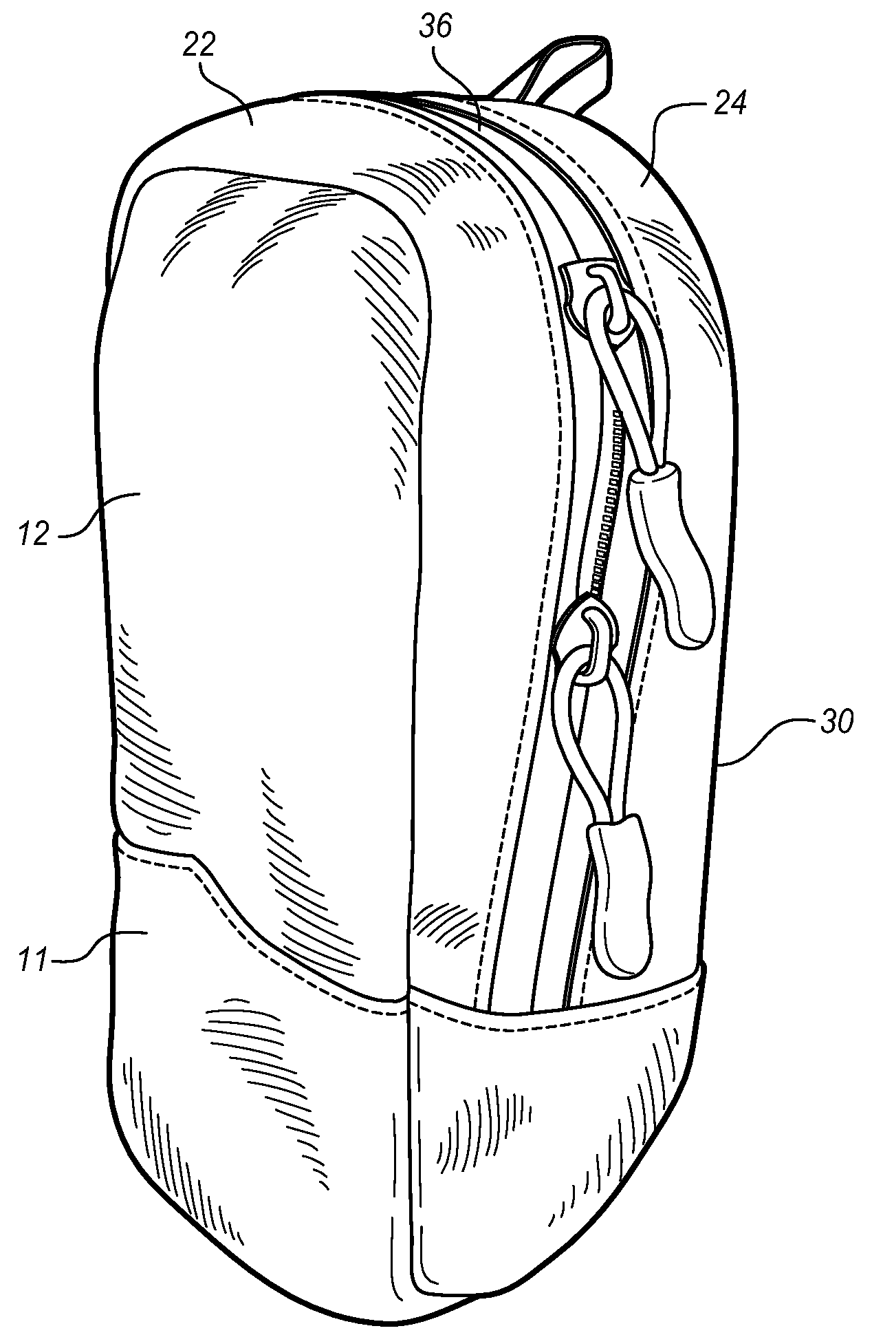
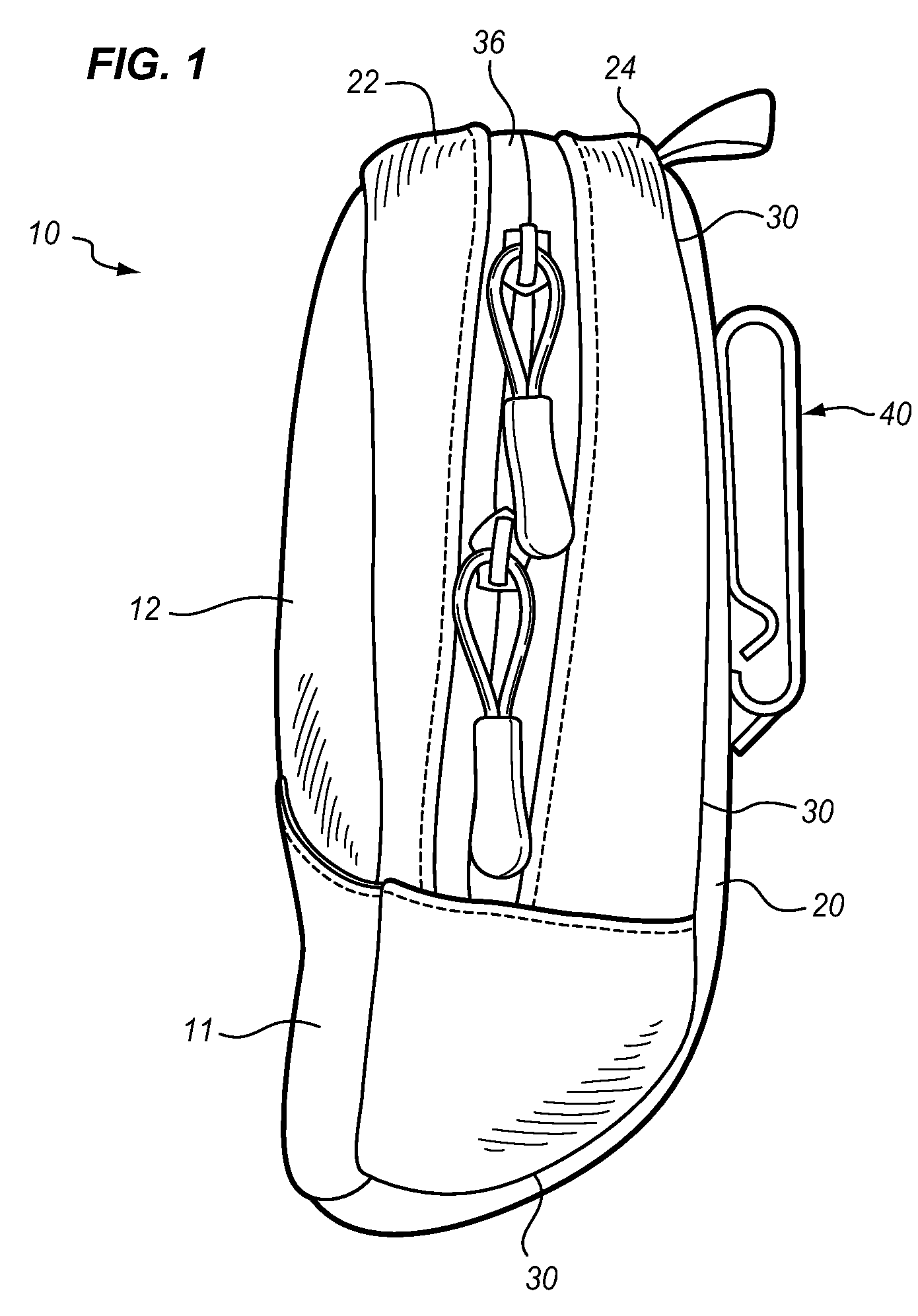
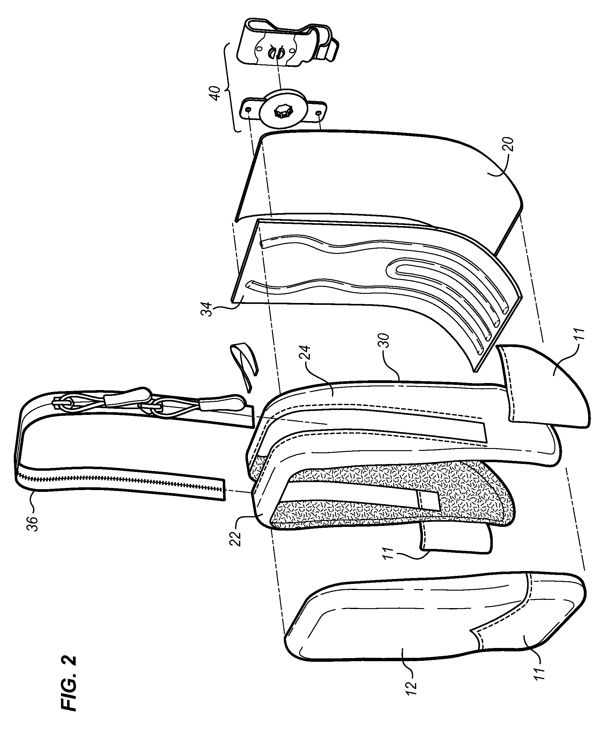
[0031]In one embodiment, shown in FIG. 1, a carrying case 10 is composed of a number of fabric panels. Carrying case 10 and the other embodiments described herein may be produced in a variety of sizes including, but not limited to, those that are approximately the size of various devices such as GPS devices, cell phones, cameras, range finders, night vision devices, etc. that they may be designed to hold. Different views of carrying case 10 can be seen in FIG. 2, which shows an exploded view of carrying case 10, and FIG. 3, which shows a front perspective view of carrying case 10.

[0032]In the embodiment shown in FIGS. 1-3, a backbone panel 20 forms the bottom and back of carrying case 10. The backbone panel 20 may be oriented in a curved L-like shape as shown in FIGS...


PUM


Abstract

A carrying case includes a backbone panel forming a back and base for the carrying case. A rear-top panel is connected to the backbone panel forming at least a portion of the sides and top of the carrying case. A left side and a right side panel are connected to the backbone panel forming a portion of the left side and right side of the carrying case, respectively. A mid-top panel is connected to the left side and right side panels, forming a portion of the sides and top of the carrying case. A mid-front panel is connected to the mid-top panel, the left side and right side panels, and the backbone panel, the mid-front panel forming the front of the carrying case. A first zipper is connected to the rear-top panel and the mid-top panel. The backbone panel, rear-top panel, left side and right side panels, mid-top panel, mid-front panel, and zipper form a first pocket in the carrying case.

Description

CROSS-REFERENCE TO RELATED APPLICATIONS[0001]This Application claims priority to US Provisional Application No. 60 / 992,005 filed on Dec. 3, 2007, the entire disclosure of which is hereby incorporated by reference.BACKGROUND OF THE INVENTION[0002]Hand-held electronic apparatus, such as GPS devices, cell phones, digital cameras, and digital binoculars, have become a ubiquitous device in modern society. The quantity and variety of hand-held electronic apparatus have increased exponentially due to practicality, cost effectiveness, and convenience of use.[0003]Many hunters, campers, and hikers may employ a variety of hand-held electronic devices. These devices vary in durability, and even those devices that are more durable may still become scratched when unprotected. Such devices may include rangefinders, night-vision goggles, cameras, spotting scopes, GPS devices, and communication devices (including two-way radios, cell phones, and satellite phones). It may be desirable to carry such ...

Claims


Application Information

Patent Timeline
IPC IPC(8): A45F5/00A45C11/00D05B23/00
CPCA45C15/06A45F5/02A45F2200/0566A45F2005/025A45F5/021
Inventor BOYD, MICHAELBALCHUNAS, DENNISCASE, RICHARD N.
Owner NITE IZE
Why Eureka
Try Eureka