
Power control system, power control apparatus, power control method and storage medium

a power control system and power control technology, applied in high-level techniques, instruments, data switching details, etc., can solve the problems of inability to carry out power control, excessive power equipment in the machine room, and increase in consumed power. , to achieve the effect of high reliability

Inactive Publication Date: 2009-05-28
NEC CORP
View PDF18 Cites 23 Cited by
  • Summary
  • Abstract
  • Description
  • Claims
  • Application Information

AI Technical Summary

Benefits of technology

[0007]Accordingly, it is an object of the present invention to enable adequate distribution of a limited power according to the operational states of individual devices while keeping a high reliability.

Problems solved by technology

In a machine room where a plurality of computers are sited, an increase in consumed power is becoming a significant problem.
Therefore, setting the maximum suppliable power value to the sum of the rated power values of the individual computers brings about a problem such that the power equipment in the machine room becomes excessive.
When the computer fails, therefore, power control cannot be carried out at all, resulting in a low reliability.
While multiplexing of computers having the master management modules mounted therein can overcome the above problem, the configuration becomes complex.

Method used


Image

  • Power control system, power control apparatus, power control method and storage medium
  • Power control system, power control apparatus, power control method and storage medium
  • Power control system, power control apparatus, power control method and storage medium

Examples


first embodiment

Configuration of First Embodiment of the Invention

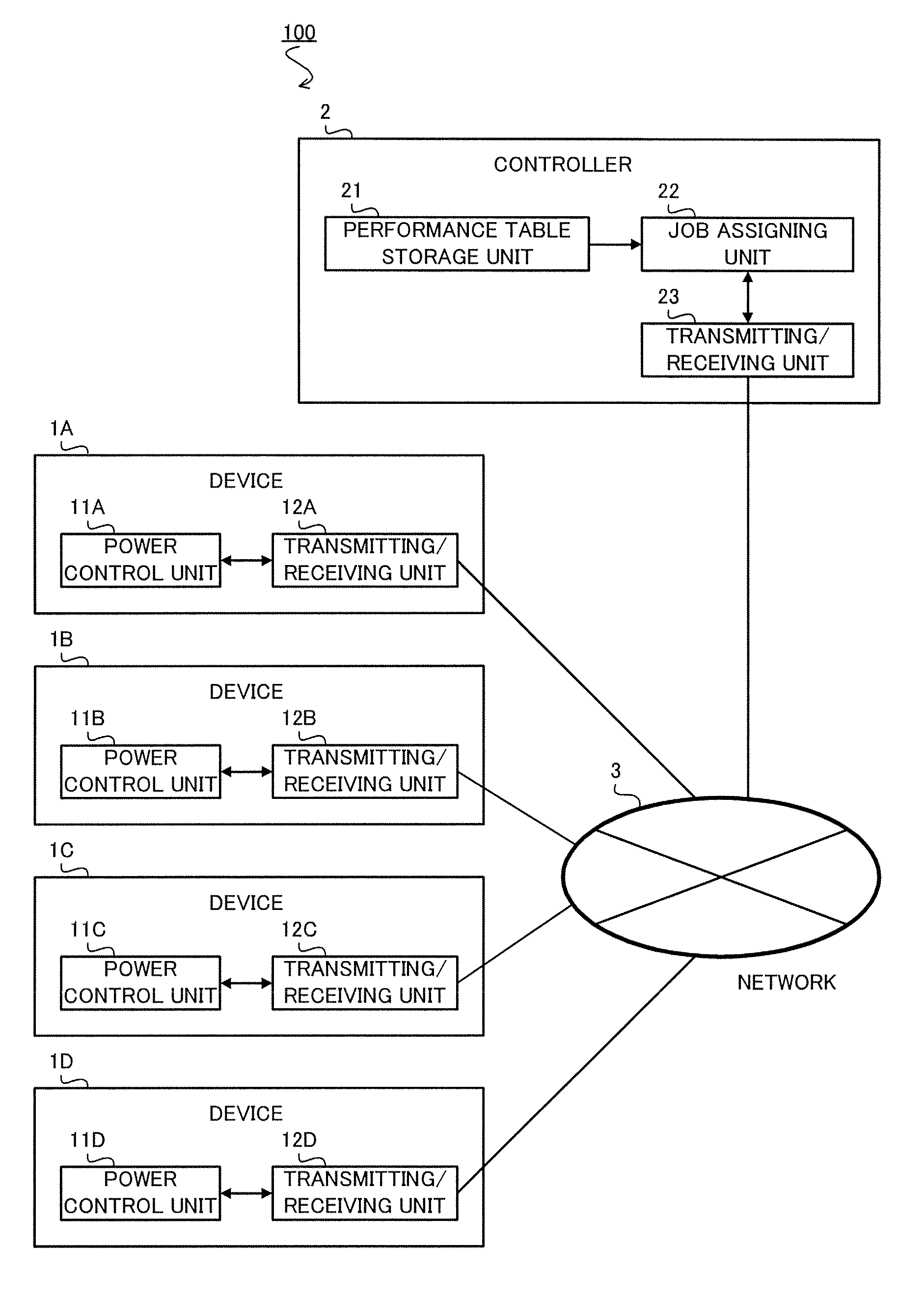
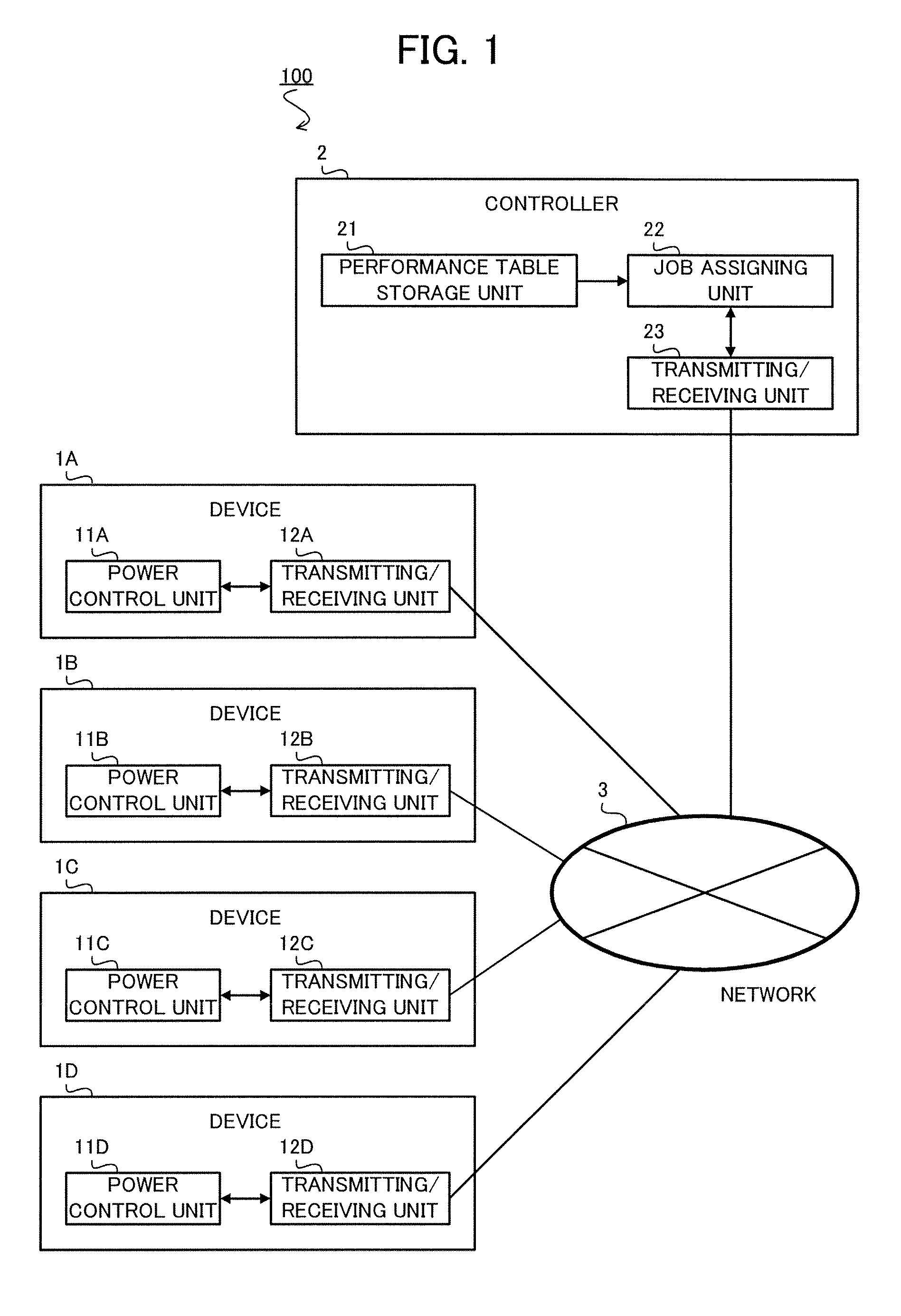
[0034]FIG. 1 is a block diagram exemplifying one example of the configuration of a power control system according to the first embodiment. As shown in FIG. 1, a power control system 100 has a plurality of devices 1A to 1D, and a controller 2, which are connected to one another over a network 3.

[Configuration of Devices 1A to 1D]

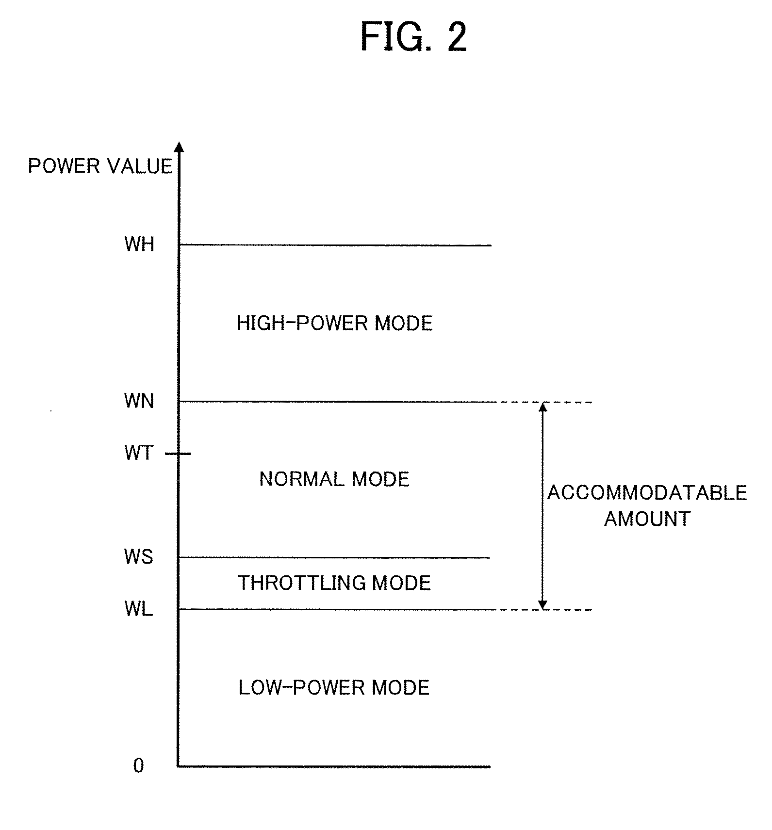
[0035]The devices 1A to 1D are, for example, computers which execute jobs dispatched from the controller 2. The devices 1A to 1D respectively have power control units 11A to 11D, and transmitting / receiving units 12A to 12D.

[0036]The transmitting / receiving units 12A to 12D have functions of transmitting and receiving data over the network 3.

[0037]Each of the power control units 11A to 11D has a function of changing the operational mode of the respective one of the devices 1A to 1D to one of a low-power mode, a normal mode, a high-power mode and a throttling mode. The power control units 11A to 11D change the op...

second embodiment

of the Invention

[0090]The second embodiment of the present invention will be described below. The feature of this embodiment lies in that the low-power mode is separated into a plurality of levels.

[0091]FIG. 9 is a block diagram exemplifying one example of the configuration of a power control system according to the second embodiment. As shown in FIG. 9, a power control system 100 has a plurality of devices 1Aa to 1Da, and a controller 2, which are connected to one another over a network 3. The devices 1Aa to 1Da respectively have power control units 11Aa to 11Da, and transmitting / receiving units 12A to 12D.

[0092]FIG. 10 shows the configuration of power control units 11Aa to 11Da used in the embodiment.

[0093]The power control units 11Aa to 11Da used in the second embodiment differ from the power control units 11A to 11D used in the first embodiment in that each power control unit includes a mode controller 113a, a mode changeover unit 114a and a load threshold value storage unit 117...


PUM


Abstract

A power control system for a network system in which a plurality of devices are connected over a network can adequately distribute limited power according to the operational state of each device while keeping a high reliability. A device operating in normal mode broadcasts a power accommodation request when the power of the device is insufficient. Upon reception of the power accommodation request, devices operating in low-power mode send accommodatable power values to the requesting device, and sends a low-power mode fixation notification indicating that operational mode is fixed to the low-power mode to a controller. Upon reception of the low-power mode fixation notification from the notifying devices, the controller sets a job assignment ratio to the notifying devices lower than that of the requesting device.

Description

BACKGROUND OF THE INVENTION[0001]1. Field of the Invention[0002]The present invention relates to a power control technique for a network system in which a plurality of devices, such as computers, are connected over a network.[0003]2. Description of the Related Art[0004]Recently, as the performance of computers is enhanced, the consumed power becomes greater. In a machine room where a plurality of computers are sited, an increase in consumed power is becoming a significant problem. In general, at the time of designing a machine room, the maximum suppliable power value (the sum of the values of power that can be supplied to the individual computers) is set to the sum of the rated power values of the individual computers. However, actually, each computer does not consistently need a rated power value, it is rare for all of the computers to use the rated power value at a time. Therefore, setting the maximum suppliable power value to the sum of the rated power values of the individual co...

Claims


Application Information

Patent Timeline
IPC IPC(8): G06F1/00G06Q50/00G06Q50/06H02J3/00H02J13/00
CPCG06F1/266G06F1/3203Y02B60/34H04L41/0893H04L12/12Y02D30/50
Inventor UCHIDA, KOHEI
Owner NEC CORP
Learn More