
Electrostatically atomizing device

Inactive Publication Date: 2009-05-28
PANASONIC CORP
View PDF6 Cites 1 Cited by
  • Summary
  • Abstract
  • Description
  • Claims
  • Application Information

AI Technical Summary

Benefits of technology

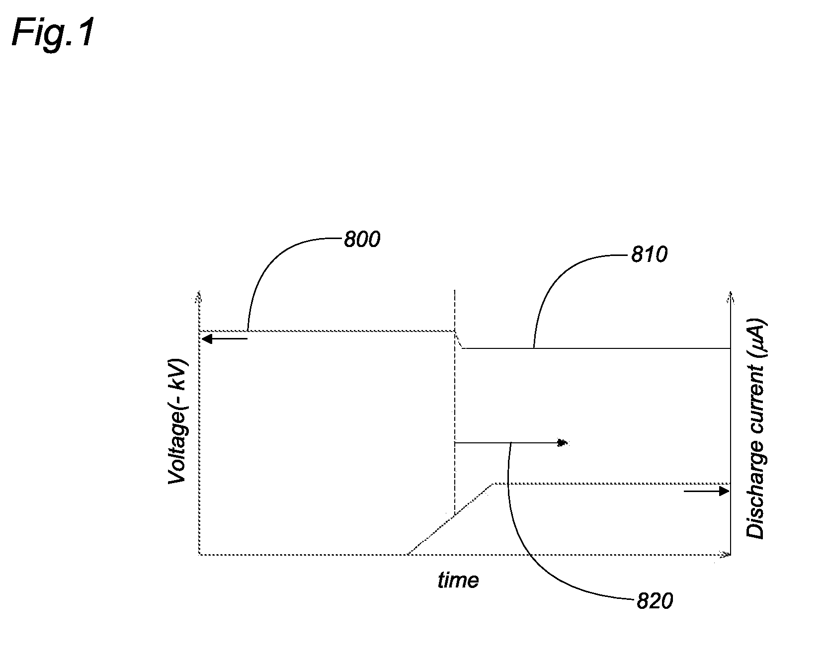
[0005]The invention is achieved to solve the above mentioned problem. The object of the invention is to provide an electrostatically atomizing device which is configured to generate the mist of the charged minute water particles at short times from the start of the device.

Problems solved by technology

However, the prior art electrostatically atomizing device takes time to generate the mist of the charged minute water particles.
That is, it is impossible for the electrostatically atomizing device to immediately generate the mist of the charged minute water particles after initiation of a device operation.

Method used


Image

  • Electrostatically atomizing device
  • Electrostatically atomizing device
  • Electrostatically atomizing device

Examples


embodiment

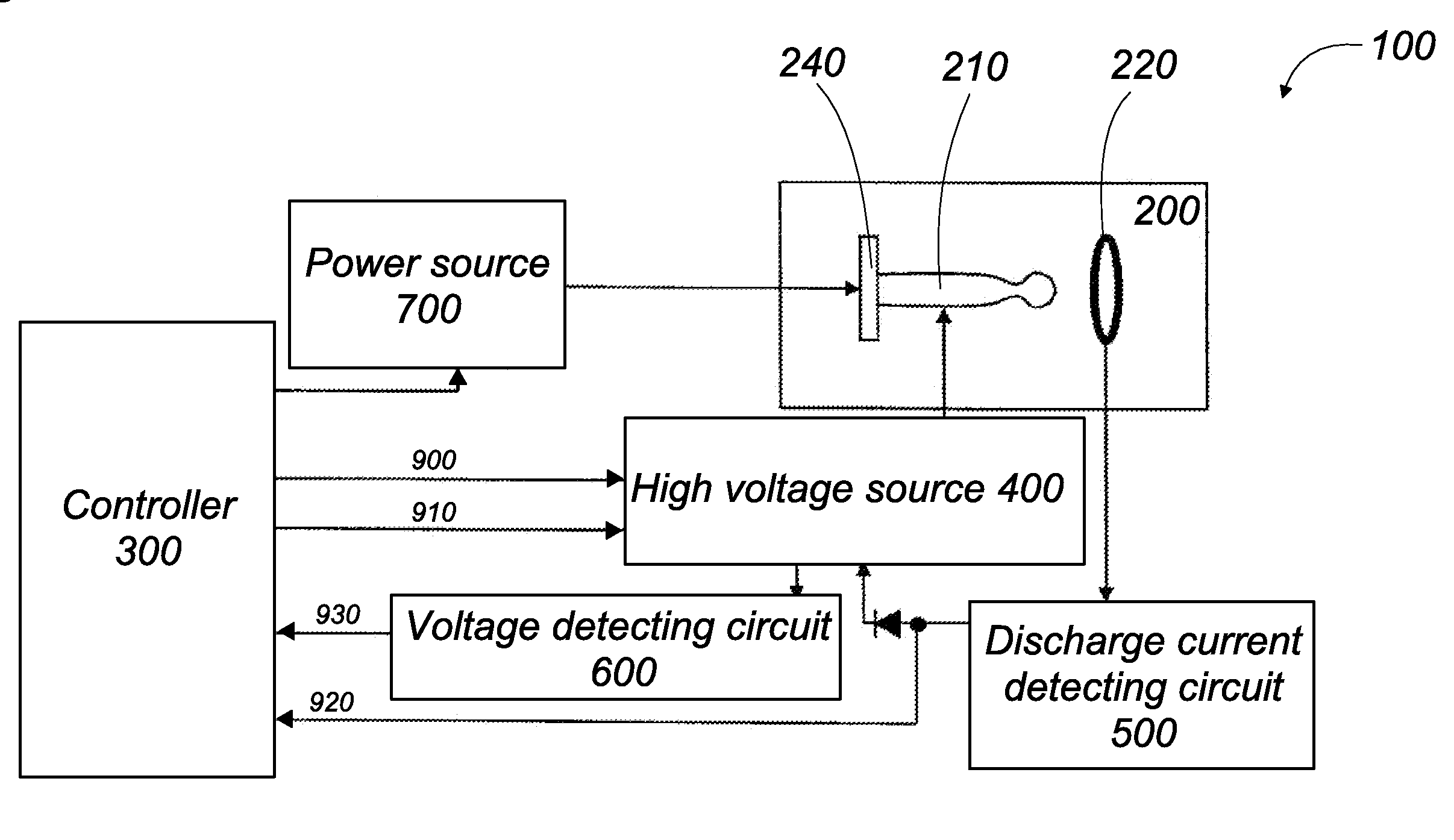
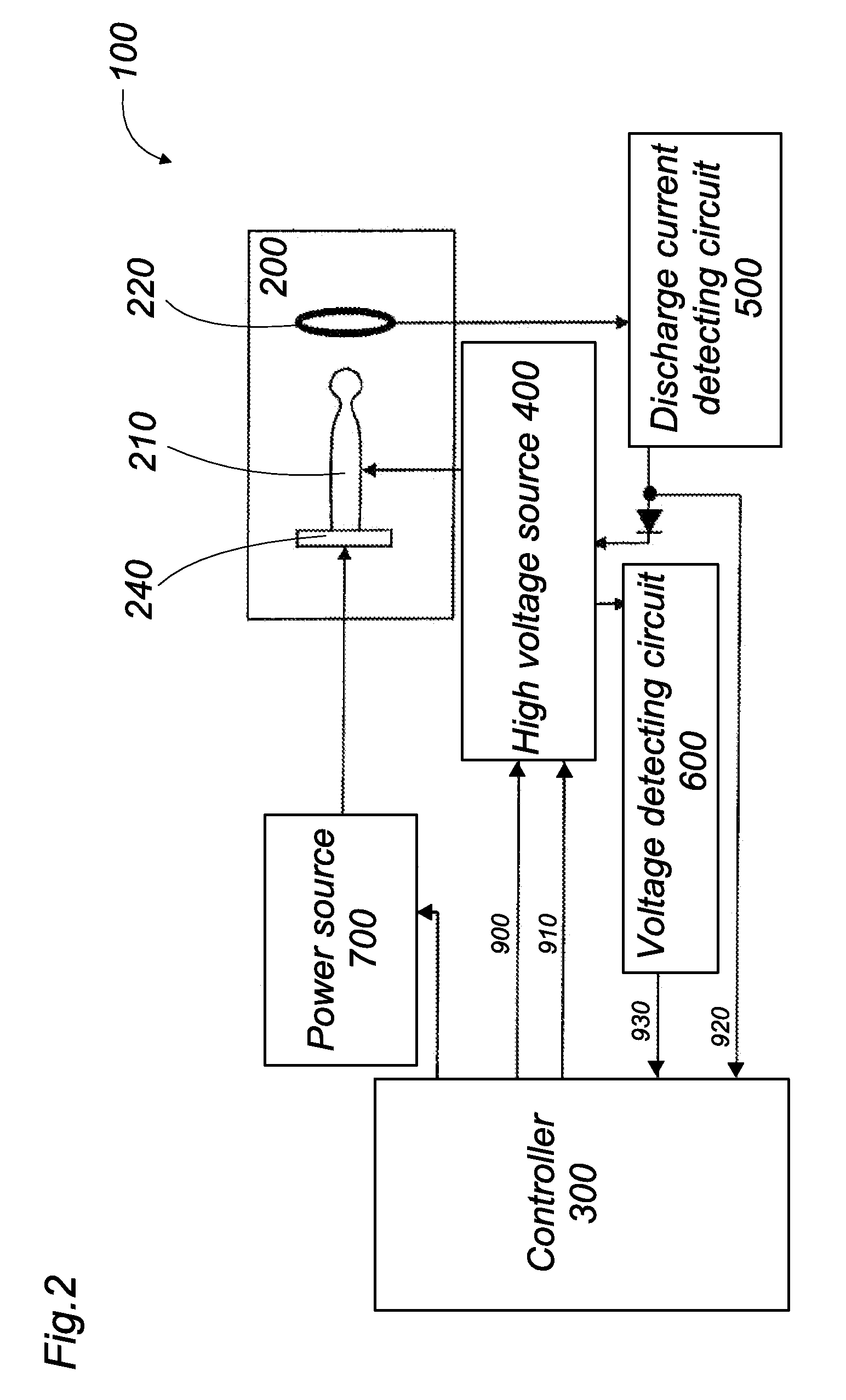
[0028]FIG. 2 shows the electrostatically atomizing device 100 in this invention. The electrostatically atomizing device 100 in this embodiment comprises an atomizing unit 200, a controller 300, a high voltage source 400, a discharge current detecting circuit 500, a voltage detecting circuit 600, and a power source 700.

[0029]FIG. 6 shows the atomizing unit 200. The atomizing unit 200 is provided for generating a mist of charged minute water particles. The atomizing unit 200 comprises an emitter electrode 210, an opposed electrode 220, an atomizing barrel 230, and a Peltier module 240. It is noted that the Peltier module 240 functions as a water supply means.

[0030]The atomizing barrel 230 has tube shape. The atomizing barrel 230 incorporates the emitter electrode 210, the opposed electrode 220, and the Peltier module 240. The atomizing barrel 230 is formed at its circumference wall with apertures 231. The apertures 231 are configured to pass the air from an outside of the atomizing ba...


PUM


Abstract

The electrostatically atomizing device in this invention comprises an emitter electrode, a water supply means, a high voltage source, and an atomization detecting means and further comprises a controller. The water supply means is configured to supply water to the emitter electrode. The high voltage source is configured to apply a high voltage to the emitter electrode so as to electrostatically atomize the water on the emitter electrode. The atomization detecting means is configured to detect a condition where the water is electrostatically atomized from the emitter electrode. The controller is configured to apply a starting voltage upon energization of the device. The controller is configured to apply an operating voltage upon recognition of the condition. The starting voltage is configured to be higher than the operating voltage. With this configuration, it is possible to obtain the electrostatically atomizing device which is configured to generate a mist of charged minute water particles immediately upon energization of the electrostatically atomizing device. It is possible to obtain the electrostatically atomizing device which is configured to generate the mist of the charged minute water particles stably upon recognition of the condition.

Description

TECHNICAL FIELD[0001]This invention relates to an electrostatically atomizing device being configured to generate a mist of the charged minute water particles by an electrostatically atomization.BACKGROUND ART[0002]Japanese patent application publication No. 2007-21370A discloses a prior art electrostatically atomizing device. The electrostatically atomizing device is configured to generate the mist of the charged minute water particles. The prior art electrostatically atomizing device comprises an emitter electrode, an opposed electrode, a water supply means, a controller, and a high voltage source. The opposed electrode is disposed in an opposed relation to the emitter electrode. The high voltage source is configured to apply voltage between the emitter electrode and the opposed electrode. The water supply means is configured to supply water to the emitter electrode.[0003]After energization of the electrostatically atomizing device, the controller starts the high voltage source to...

Claims


Application Information

Patent Timeline
IPC IPC(8): H05F7/00
CPCB05B5/006B05B5/057
Inventor URATANI, YUTAKAOBATA, KENJIISAKA, ATSUSHI
Owner PANASONIC CORP
Learn More