Hand-held power tool having auxiliary handle with clamping band

a technology of which is applied in the field of hand-held power tools with auxiliary handle and clamping band, can solve the problems of loosening of locking screw, and achieve the effects of high locking force, high elasticity, and low bending stiffness

Inactive Publication Date: 2009-05-28
HILTI AG
View PDF10 Cites 12 Cited by
  • Summary
  • Abstract
  • Description
  • Claims
  • Application Information

AI Technical Summary

Benefits of technology

[0010]Advantageously, there are provides at least two different types of cams. The different types of cams can include elongate transverse cams extending transverse to the loop, elongate cams extending along the loop, and spherical cap-shaped cams. These cams permit to achieve (with respect to the locking flange) both axial and tangential formlocking action, without increasing bending stiffness along the loop.
[0012]Advantageously, the manually tensioning means includes a rotatable hand grip and a locking screw for tensioning the band in response to a respective rotation of the hand grip. Thereby, the locking is easily carried out by rotating the hand grip.
[0014]Advantageously, the clamping band has two, radially outwardly projecting, guide noses provided respectively on its two opposite ends. Thereby, upon releasing the clamping band, the open width of the two ends of the clamping band is determined by the guide surfaces of the locking flange. Thereby, falling of the locking screw off the head upon opening of the receiving openings can be prevented.

Problems solved by technology

This can lead to loosening of the locking screw which is formlockingly received in receiving openings provided in the ends of the clamping band which are guided along the head upon a wider opening of the clamping band loop.

Method used


Image

  • Hand-held power tool having auxiliary handle with clamping band
  • Hand-held power tool having auxiliary handle with clamping band
  • Hand-held power tool having auxiliary handle with clamping band

Examples


Embodiment Construction

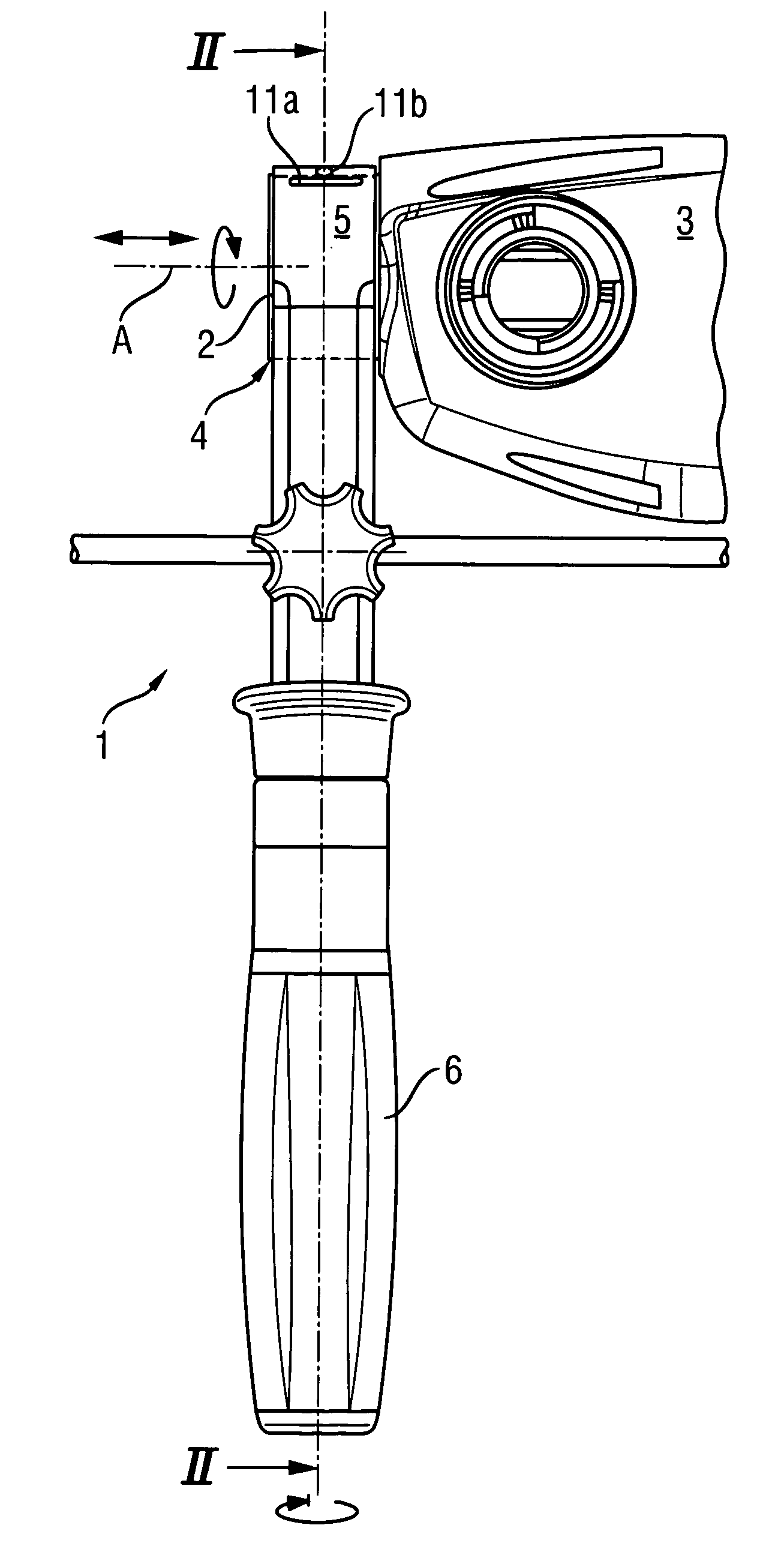
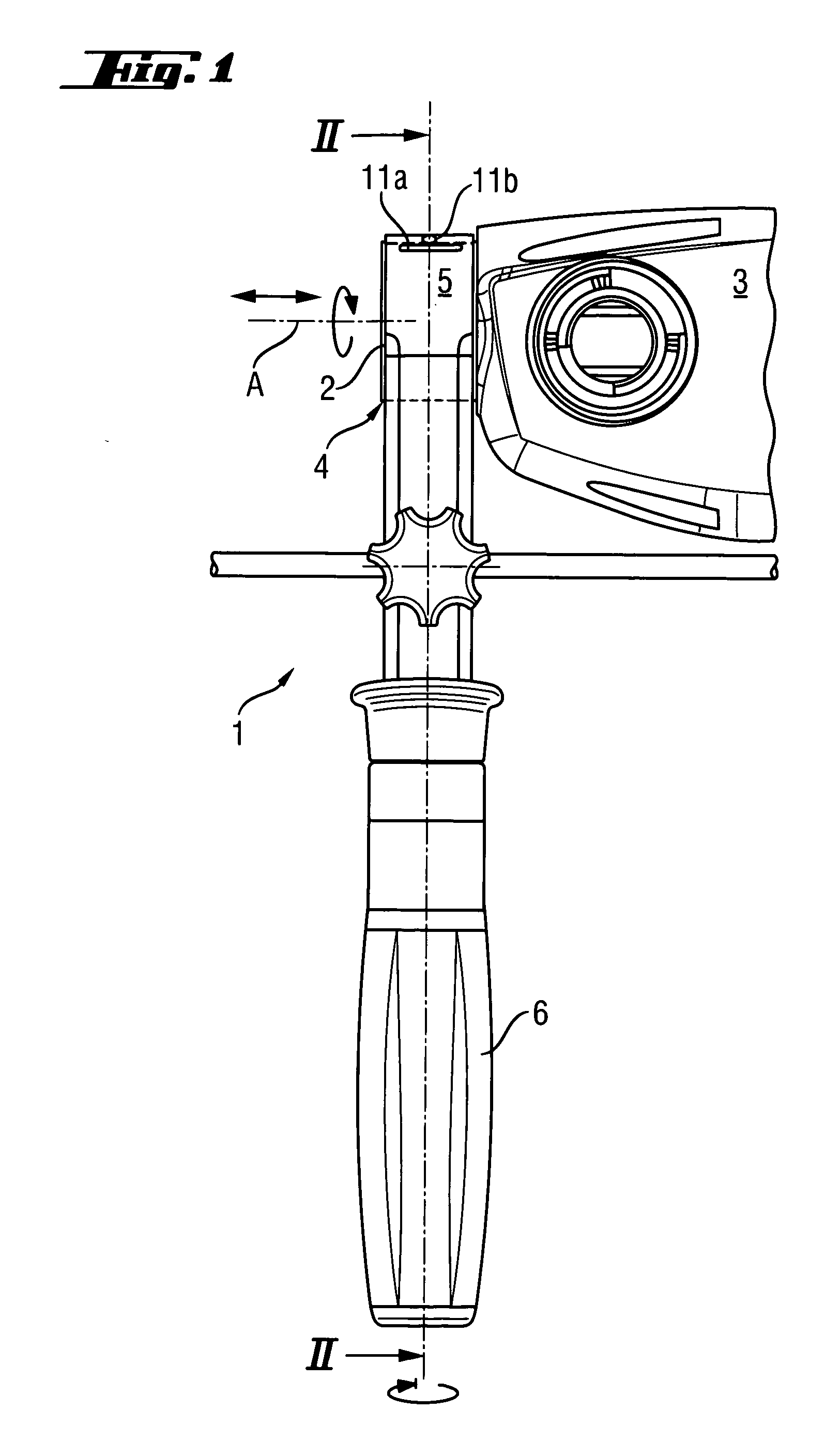
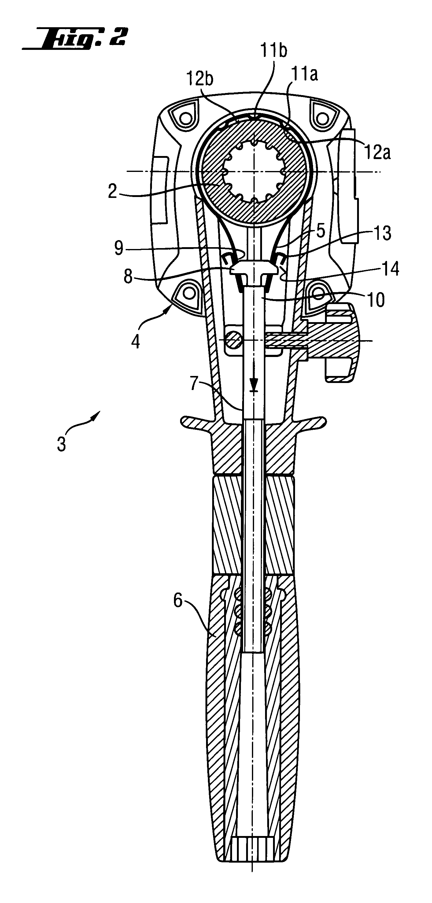
[0021]A hand-held power tool 3, which is formed as a hammer drill and is only partially shown in FIGS. 1 and 2, has a locking flange 2 to which an auxiliary handle 1 that is positioned relative to the operational axis A of the power tool 3, is secured. The auxiliary handle 1 has a head 4 formlockingly adapted to the locking flange 2.

[0022]In the head 4, a loop-shaped clamping band 5, which is formed of spring steel, is displaceably arranged. The clamping band 5 is tensioned by a manual rotation of a hand grip 6, with a head 8 of a locking screw 7 and which engages in receiving openings 9 in both ends 10 of the clamping band 5. On the clamping band 5, on a loop section opposite the handle 6, there are provided a plurality of longitudinally offset, radially inwardly projecting cams 11a, 11b.

[0023]The cams 11a, 11b formlockingly engage in associated recesses 12a, 12b in the locking flange 2 of the power tool 3. The locking band 5 has, on both of its ends 10, projecting radially outwar...


PUM


Abstract

A hand-held power tool includes a locking flange (2), and an auxiliary handle (1) securable to the locking flange (2) and having a head (4), a loop-shaped clamping band (5) located in the head (4), at least one, radially inwardly projecting cam (11a, 11b) provided on the clamping band (5) and formlockingly engageable in an associated recess (12a, 12b) formed in the locking flange (2), and a member for manually tensioning the clamping band (5).

Description

BACKGROUND OF THE INVENTION[0001]1. Field of the Invention[0002]The present invention relates to a hand-held power tool with an auxiliary handle having a clamping band and, in particular, to a hammer drill.[0003]2. Description of the Prior Art[0004]Usually, an auxiliary handle is secured on a cylindrical locking flange of a power tool with a clamp, a clamping yoke, or a clamping band. Often, on the auxiliary handle, there is also provided a depth stop in form of a rigid, displaceably securable bar.[0005]European Publication EP 0 132 593 discloses an auxiliary handle securable on a locking flange of a hand-held power tool with a loop-shaped clamping band. The clamping band is tensioned by a locking screw upon rotation of a hand grip. The auxiliary handle has a head that is formlockingly adapted to the locking flange and, with the auxiliary handle secured in a predetermined manner, is positioned relative to the rotational axis of the power tool. Additionally, a depth stop is formlocki...

Claims


Application Information

Patent Timeline
IPC IPC(8): B25D17/00
CPCB23B45/001B25D17/04B25F5/003B25F5/026B25D2222/21
Inventor KELLER, VALENTINSCHILLING, PASCALLUDWIG, MANFREDHOFBRUCKER, THOMAS
Owner HILTI AG
Why Eureka
Try Eureka