X-ray tube having a focal spot proximate the tube end

a focal spot and x-ray tube technology, applied in the field of x-ray tubes, can solve the problems of exacerbated above imaging challenges of known tube designs, unconfigured tube designs that minimize the spacing between the chest wall, and suffer from image quality degradation, so as to reduce the spacing, improve tissue coverage, and reduce the effect of spacing

Active Publication Date: 2009-05-21
VAREX IMAGING CORP
View PDF17 Cites 4 Cited by
  • Summary
  • Abstract
  • Description
  • Claims
  • Application Information

AI Technical Summary

Benefits of technology

[0013]The present invention has been developed in response to the above and other needs in the art. Briefly summarized, embodiments of the present invention are directed to an x-ray tube having a reduced spacing between the focal spot of an anode and an adjacent end wall of an evacua

Problems solved by technology

One challenge encountered with the operation of x-ray tubes, particularly tubes employed in the field of mammography, relates to the optimum positioning of the tube with respect to the patient's body (and in particular, the portion of the patient's body that is of interest) during x-ray imaging.
Conversely, should the focal spot be located a relatively large distance away from the chest wall, image quality will consequently suffer.
The above notwithstanding, known tube designs are not configured to minimize spacing between the chest wall and the focal spot of the anode.
The above imaging challenges present with known tube designs are exacerbated when the breast or other subject to be imaged is relativ

Method used


Image

  • X-ray tube having a focal spot proximate the tube end
  • X-ray tube having a focal spot proximate the tube end
  • X-ray tube having a focal spot proximate the tube end

Examples


Embodiment Construction

[0026]Reference will now be made to figures wherein like structures will be provided with like reference designations. It is understood that the drawings are diagrammatic and schematic representations of exemplary embodiments of the invention, and are not limiting of the present invention nor are they necessarily drawn to scale.

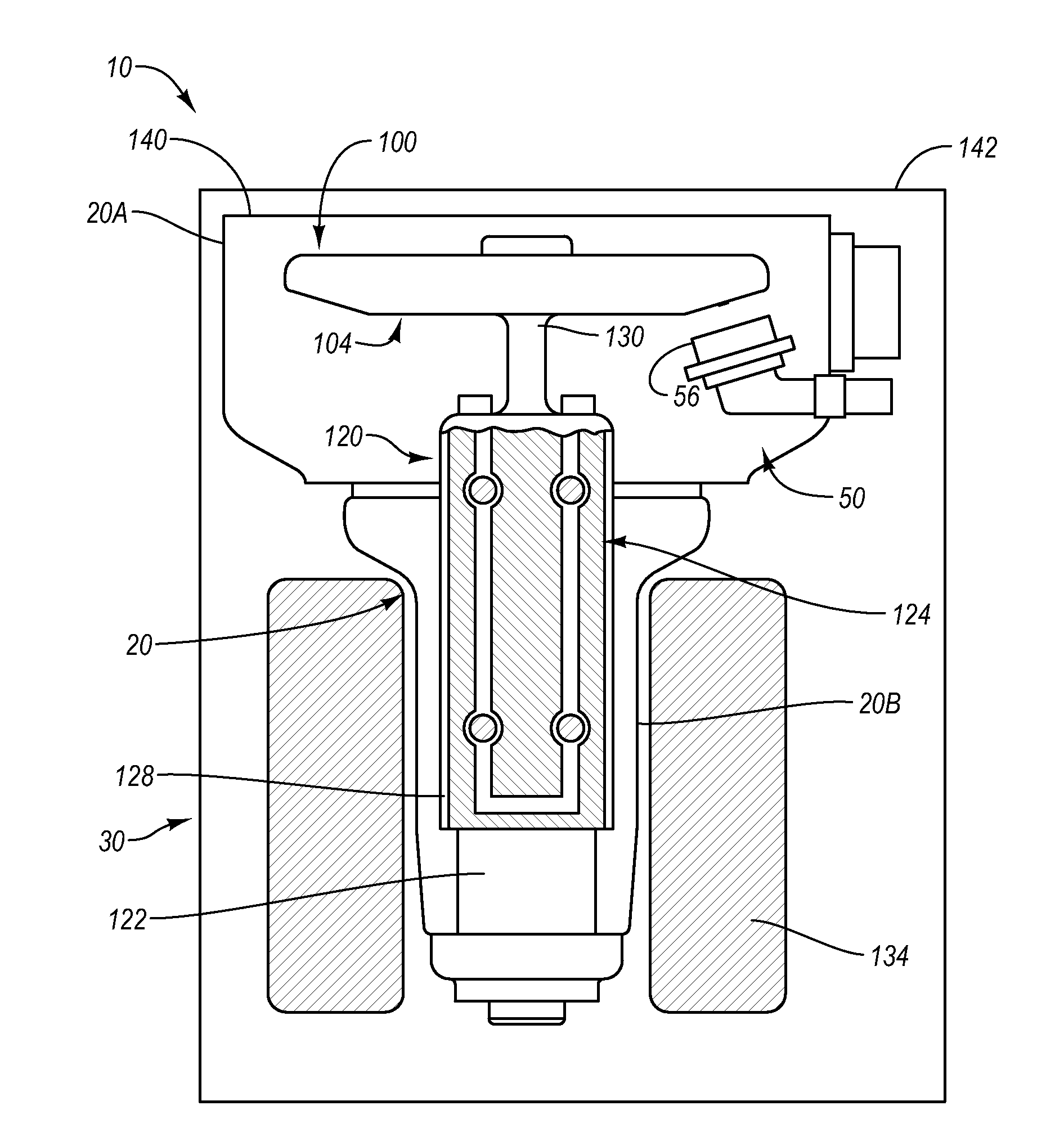
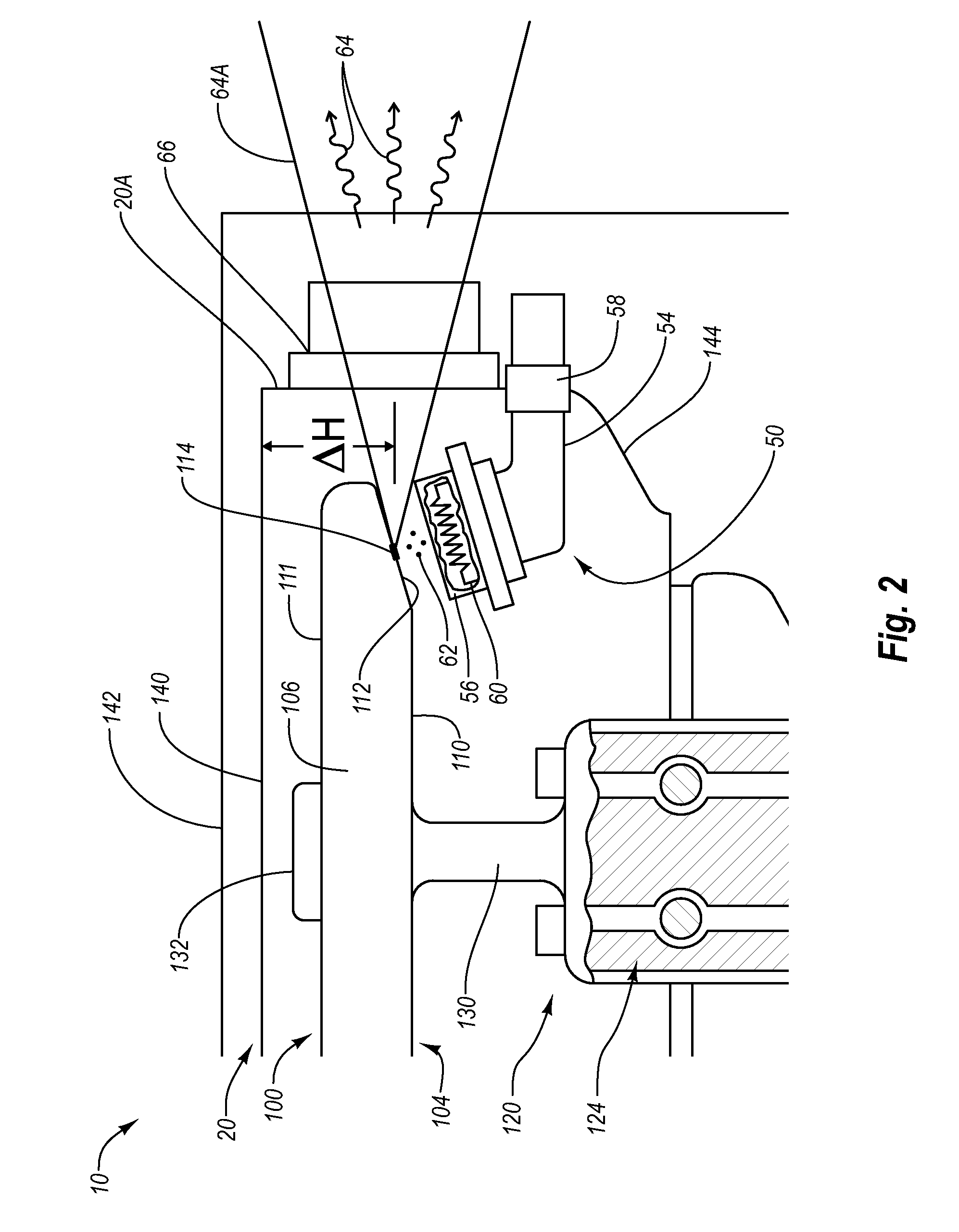
[0027]FIGS. 1-4 depict various features of embodiments of the present invention, which is generally directed to an x-ray tube configured in a manner so as to reduce the distance between an electron focal spot of the rotary anode and the nearest end of the x-ray tube. This configuration enables the x-ray tube to be placed relatively closer to the chest wall of a patient during mammography procedures, and thereby allows the central ray emitted by the tube to be substantially parallel to the chest wall. This configuration and placement results in improved mammographic imaging regardless of breast size, particularly because of the ability of disclosed embodiments...


PUM


Abstract

An x-ray tube having a reduced spacing between the focal spot of an anode and an adjacent end wall of an evacuated enclosure is disclosed. This in turn positions the tube relatively closer to the chest wall of a patient during mammography procedures. In one embodiment, the x-ray tube comprises an evacuated enclosure having first and second ends interconnected by a cylindrical side wall. The evacuated enclosure includes a rotor assembly having a bearing assembly and a stem. An anode is rotatably supported by the stem of the rotor assembly and includes a target surface and an opposite second surface. The target surface is positioned to face the bearing assembly, while the second surface is positioned to face the first end of the evacuated enclosure, with no intervening structure interposed therebetween. A cathode is included to emit electrons for impingement on a focal spot of the focal track.

Description

BACKGROUND[0001]1. Technology Field[0002]The present invention generally relates to x-ray tubes. In particular, embodiments of the present invention are directed to x-ray tube configurations that reduce the distance between the focal spot of an anode and an adjacent end of the evacuated enclosure in which the anode is disposed.[0003]2. The Related Technology[0004]X-ray generating devices are extremely valuable tools that are used in a wide variety of applications, both industrial and medical. For example, such equipment is commonly employed in areas such as medical diagnostic examination, therapeutic radiology, semiconductor fabrication, and materials analysis.[0005]Regardless of the applications in which they are employed, most x-ray generating devices operate in a similar fashion. X-rays are produced in such devices when electrons are emitted, accelerated, and then impinged upon a material of a particular composition. This process typically takes place within an x-ray tube located...

Claims


Application Information

Patent Timeline
IPC IPC(8): H01J35/06
CPCH01J35/26
Inventor VIRSHUP, GARY FREDRIC
Owner VAREX IMAGING CORP
Why Eureka
Try Eureka