Image device and lens barrel
- Summary
- Abstract
- Description
- Claims
- Application Information
AI Technical Summary
Benefits of technology
Problems solved by technology
Method used
Image
Examples
embodiment 1
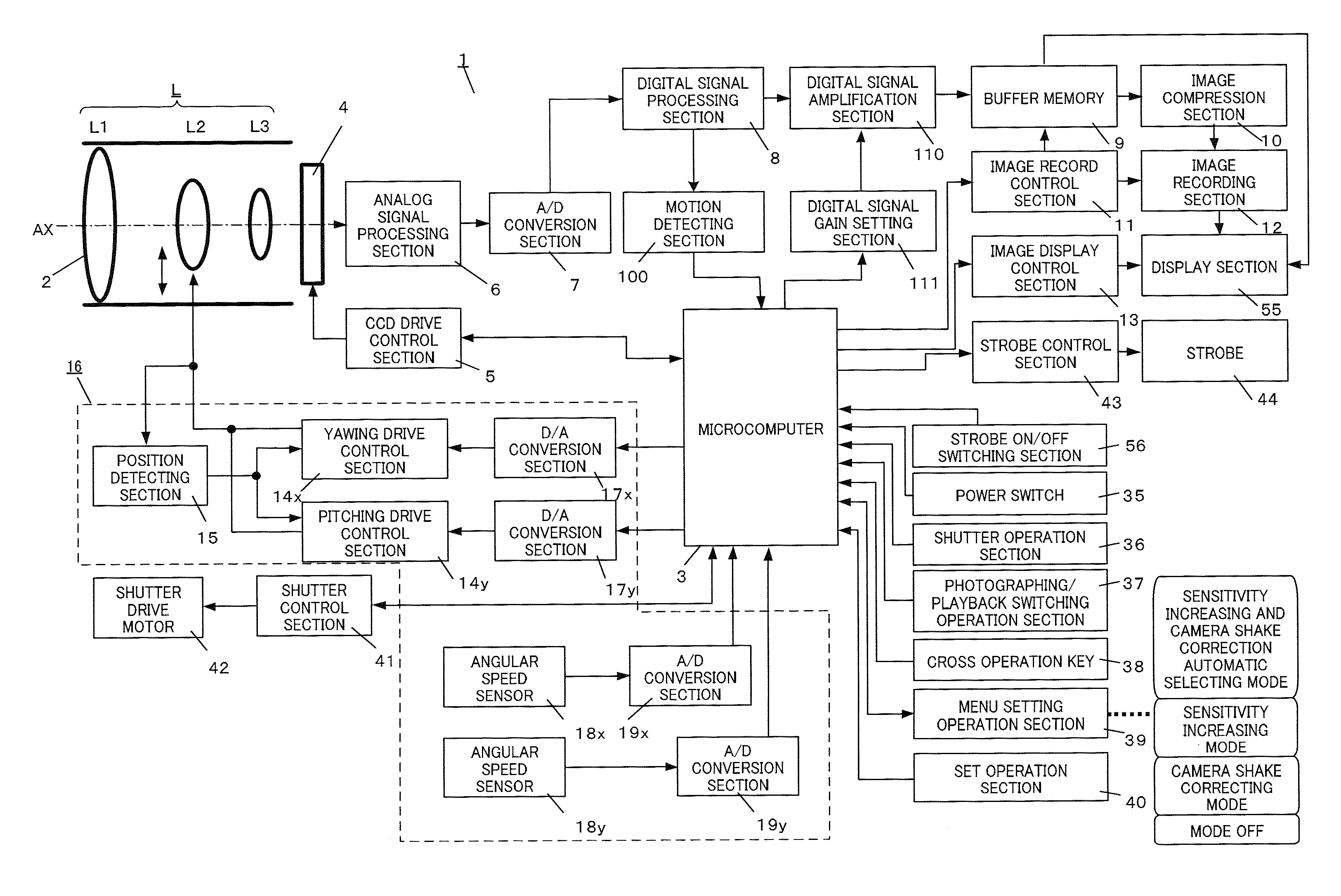
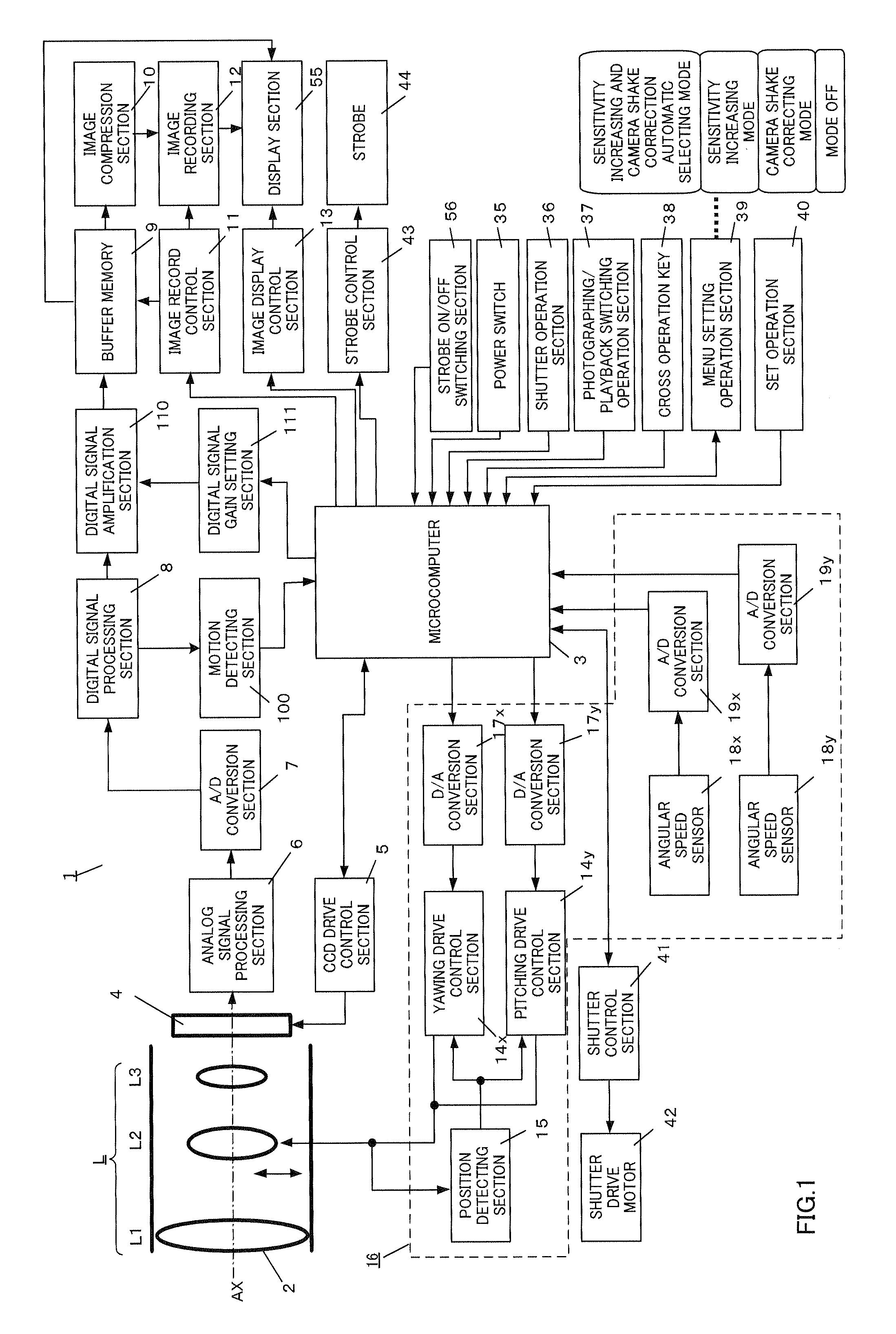
[0031]FIG. 1 is a block diagram showing the configuration of an image pickup apparatus according to an embodiment of the present invention. FIG. 2 illustrates the schematic configuration of the image pickup apparatus according to the present embodiment, where FIG. 2A shows a top view and FIG. 2B shows a rear view. The present embodiment is an example where the present invention is applied to a digital camera having a camera shake correcting function and a photographing sensitivity change function. In the following explanation, the “moving speed” of a photographing object (also referred to as “object speed”) is the moving speed of the optical image of the photographing object on the image pickup plane, caused by one of or both of camera shake and object shake.
[0032]In FIG. 1, digital camera 1 employs a configuration having image pickup optical system L, microcomputer 3, image pickup sensor 4, CCD (Charge Coupled Device) drive control section 5, analog signal processing section 6, A / D...
embodiment 2
[0085]Next, the digital camera according to Embodiment 2 will be explained. Although the digital camera according to the present embodiment has a similar basic configuration to the digital camera according to Embodiment 1, the digital camera differs in that a panning shot mode is further selectable as an photographing mode. Here, “panning shot” is a method whereby, when a fast moving photographing object is photographed, a photograph is taken by pressing shutter operation section 36 while the orientation of the camera is moved in the traveling direction, and it is possible to take a photograph by taking a photograph in the panning shot mode as if the photographing object is still and the background is flowing. In the present embodiment, the same components as those of Embodiment 1 are assigned the same reference numerals and explanations will be focused on differences from Embodiment 1.
[0086]FIG. 7 is a flowchart showing photographing processing of the digital camera according to Em...
embodiment 3
[0093]Next, the digital camera according to Embodiment 3 will be explained. Although the digital camera according to the present embodiment has a similar basic configuration to the digital configuration described in Embodiments 1 and 2, the digital camera differs in that photographing sensitivity is set according to the moving speed of the photographing object. Explanations will be focused on points different from Embodiments 1 and 2 below.
[0094]When the photographer presses shutter operation section 36 halfway, motion detecting section 100 detects the motion of the photographing object and outputs a detecting vector. Microcomputer 3 calculates moving speed Vh of the photographing object from the outputted detecting vector. Moreover, microcomputer 3 calculates the shutter speed at which no object shake occurs from moving speed Vh and sets photographing sensitivity where photographing can be taken at the calculated shutter speed. For example, when a photographing object moving slowly...
PUM
 Abstract
Description
Claims
Application Information
 - R&D
- Intellectual Property
- Life Sciences
- Materials
- Tech Scout
- Unparalleled Data Quality
- Higher Quality Content
- 60% Fewer Hallucinations
Browse by: Latest US Patents, China's latest patents, Technical Efficacy Thesaurus, Application Domain, Technology Topic, Popular Technical Reports.
© 2025 PatSnap. All rights reserved.Legal|Privacy policy|Modern Slavery Act Transparency Statement|Sitemap|About US| Contact US: help@patsnap.com


