
Shoulder-Belt-Traction Hand-Push Tool

Inactive Publication Date: 2009-05-21
TANAYA SATORU
View PDF13 Cites 8 Cited by
  • Summary
  • Abstract
  • Description
  • Claims
  • Application Information

AI Technical Summary

Benefits of technology

[0016]In view of the problems described above, an object of the present invention is to provide a shoulder-belt-traction hand-push tool that reduces burdens on the arms and the back of a user, that is inexpensive and easy to handle and that can improve operating efficiency.
[0048]The shoulder-belt-traction hand-push tool makes it possible to reduce labor involved in a hand-push operation and frees the user from an uncomfortable posture because the shoulder-belt-traction hand-push tool is pulled through a tension bar by a shoulder belt fitted around the body of a user. Thus, it effectively reduces the labor and working hours of workers and ordinary people who work for long periods of time, so there is a large possibility of becoming popular. The shoulder-belt-traction hand-push tool can be added to currently widespread hand-push tools, and integrated products can be made at the time of production, thus, it is thought highly likely to be widely used.

Problems solved by technology

However, there was a problem that when the user performs hand-push operations while walking with the snow removal tool and the snow shovel according to Patent Document 1 and 2, resistance caused by snow places a heavy load on both hands of the user.
Moreover, the user needs to lean forward because the user exerts force with both hands.
Thus, a heavy burden is imposed on the back of the user, and this may cause pain in the back.
Also, there was a problem that when a user performs hand-push operations for a prolonged period with the cleaning mop of Patent Document 3 and the water removal wiper of Patent Document 4, resistance load placed on both hands of the user becomes heavier with time, so the user needs to lean forward in the hand-push operation, and thus a heavy burden is imposed on the back of the user.
This causes the user to become extremely fatigued.
Further, there was a problem that the hand-push lawnmower of Patent Document 5 is too small to mow the lawn in a large area, and thus its efficiency is poor, so when it performs a lawn mowing operation, resistance caused by the lawn imposes a heavy burden on both hands and the back of the user.
As the electrically-operated-cart speed control device, the power-assisted cart and the one-wheel cart according to Patent Document 6 to 8 are carts driven by electric motors, there was a problem that they do not have the lightness, easy cornering and easy usability of common manually operated carts.
Also there was a problem that the carts are heavy due to the use of electric motors and batteries, and they suffer from inconvenience involved in the charging of the batteries, and since the electric motors, the batteries and other control devices are included, the one-wheel cart, the four-wheel cart, the wheelchair and the like are expensive.

Method used


Image

  • Shoulder-Belt-Traction Hand-Push Tool
  • Shoulder-Belt-Traction Hand-Push Tool
  • Shoulder-Belt-Traction Hand-Push Tool

Examples


Embodiment Construction

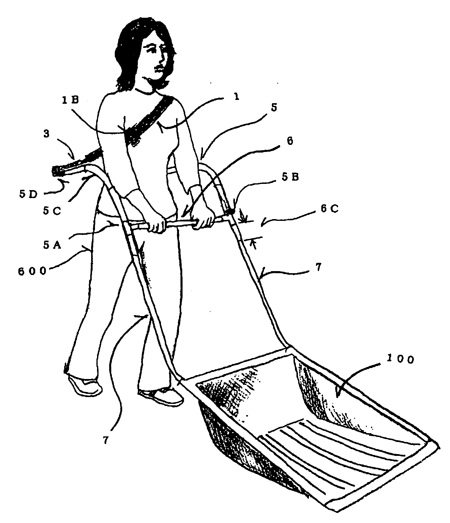
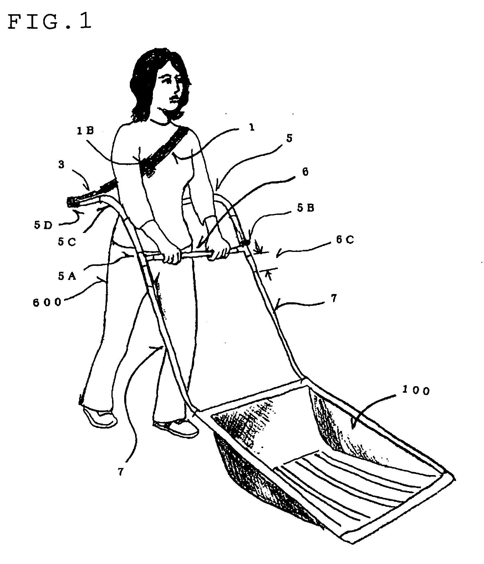
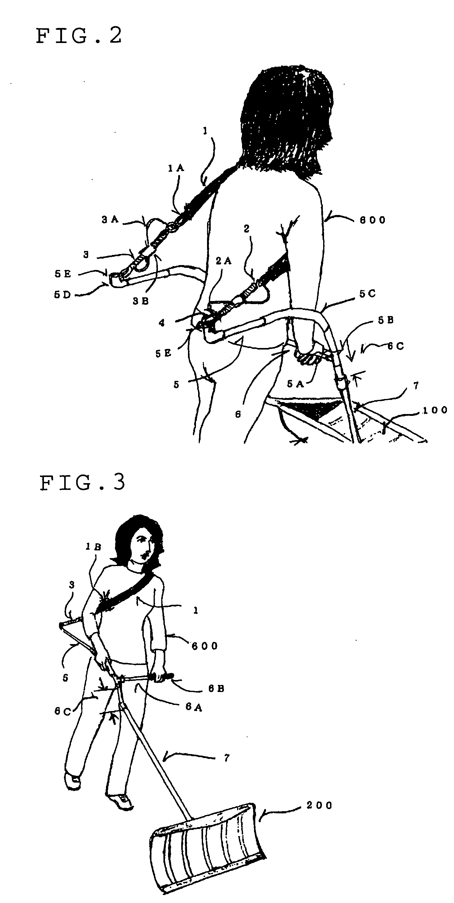
[0029]Embodiments of the present invention will be described below with reference to the accompanying drawings. FIGS. 1 to 13 shows the shoulder-belt-traction hand-push tool according to the embodiments of the invention. As shown in FIGS. 1 and 2, the shoulder-belt-traction hand-push tool is composed of a large snow removal tool 100.

[0030]As shown in FIG. 1, in the large snow removal tool 100, one end of a tension bar 5 of a pipe member is inserted into a hollow tension bar connection section 5A disposed at both ends of a handle 6. A tension bar elbow 5D of the L-shaped pipe member is attached to the other end of the tension bar 5 connected by a tension bar intervening metal member 5C. A tension bar ring metal member 5E of the ring-shaped metal member as a connecting section or, to a shoulder belt 1 is attached to both tension bar elbow 5D fitted to the tension bar 5. The shoulder belt 1 of the ring-shaped member has a shoulder belt tackle 1B that can adjust the shoulder belt 1 in l...


PUM


Abstract

A traction tension bar of a pipe member is connected to an end of a handle of the hand-push tool. A tension bar ring metal member of a ring-shaped metal member is disposed at an end of the tension bar extending backward. A shoulder belt is connected through a shock absorption spring to the tension bar ring metal member by an attachment hook, and can be fitted around the body of the user. The user fits the shoulder belt around the body, holds the handle of the hand-push tool with both hands, leans forward and puts their weight into the shoulder belt to produce traction, and starts to walk while putting their weight into the shoulder belt to pull the hand-push tool.

Description

BACKGROUND OF THE INVENTION[0001]1. Field of the Invention[0002]The present invention relates to a shoulder-belt-traction hand-push tool.[0003]2. Description of the Related Art[0004]Conventionally, many hand-push tools have been invented. For example, highly efficient snow removal tools and snow removal accessories are disclosed (for example, see Patent Document 1). Also disclosed are scoop type snow shovels (for example, see Patent Document 2) with which a series of snow removal operations such as for pushing and separating snow, pushing out snow, collecting snow and scooping and disposing of snow can be performed in an integrated manner; they help reduce the labor of removing snow and streamline snow removal operations and lessen the labor of removing snow. The following hand-push tools are also disclosed: mop handle attaching devices (for example, see Patent Document 3) that effectively use force exerted by a user and prevent the mop from falling down; water removal floor wipers ...

Claims


Application Information

Patent Timeline
IPC IPC(8): E01H5/02
CPCA01D34/82A47L13/11Y10T16/447B62B5/068E01H5/02A47L13/20
Inventor TANAYA, SATORU
Owner TANAYA SATORU
Learn More