
Robotic Cleaning Device

a cleaning device and robot technology, applied in the direction of vehicle position/course/altitude control, process and machine control, instruments, etc., can solve the problems of prolonging the cleaning time, wasting time and energy, and device not moving clear

Active Publication Date: 2009-05-21
AB ELECTROLUX
View PDF16 Cites 61 Cited by
  • Summary
  • Abstract
  • Description
  • Claims
  • Application Information

AI Technical Summary

Benefits of technology

[0009]Due to the cleaning device being arranged to rotate around one of two main turn axis in the rear portion of the device in combination with the side walls being configured in coordination with said rotation axis, the cleaning device is able to move clear from an obstacle without having to stop. In addition, this combination of turning axis locations and side wall configuration makes it possible to move the device clear of most obstacles by a turn less than 90°.
[0033]According to one embodiment of the invention, the centre of gravity is located at a distance form each of the main left-turn axis and the main right-turn axis. Thereby, the cleaning device will experience a turning momentum when turning around one of the main turn axes due to momentum forces. This turning momentum will contribute to the low energy consumption of the cleaning device. If the distance between the centre of gravity to the respective main turning axis is equal, the experienced momentum will be equal during left and right turns around the corresponding main turn axis.

Problems solved by technology

A problem with this known robotic cleaning device is that it is time and energy consuming to steer the device around obstacles, for example table legs or chair legs, which are common in normal home environments.
This is especially a problem with battery operated robotic cleaning devices, since the batteries thereof often have to be reloaded or recharged, which extends the cleaning time even more.
However, since the device in that case will not turn around a central axis, a problem with this way of operation is that the device will not move clear of the obstacle, but will be pushed backwards by the obstacle during the rotation or will even get stuck.

Method used


Image

  • Robotic Cleaning Device
  • Robotic Cleaning Device
  • Robotic Cleaning Device

Examples


Embodiment Construction

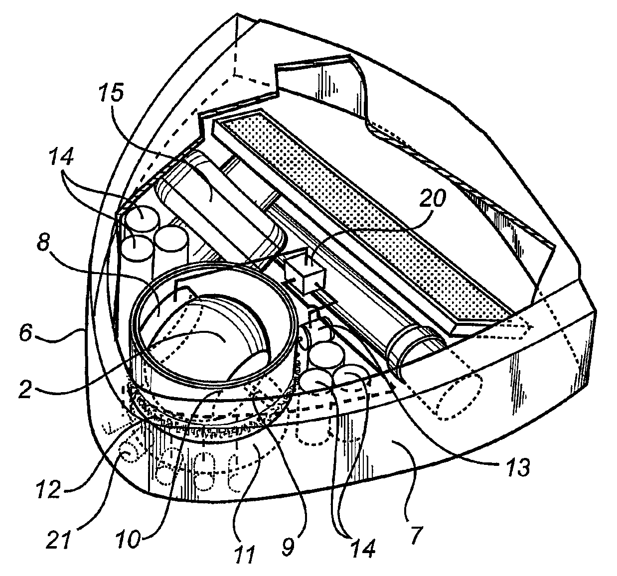
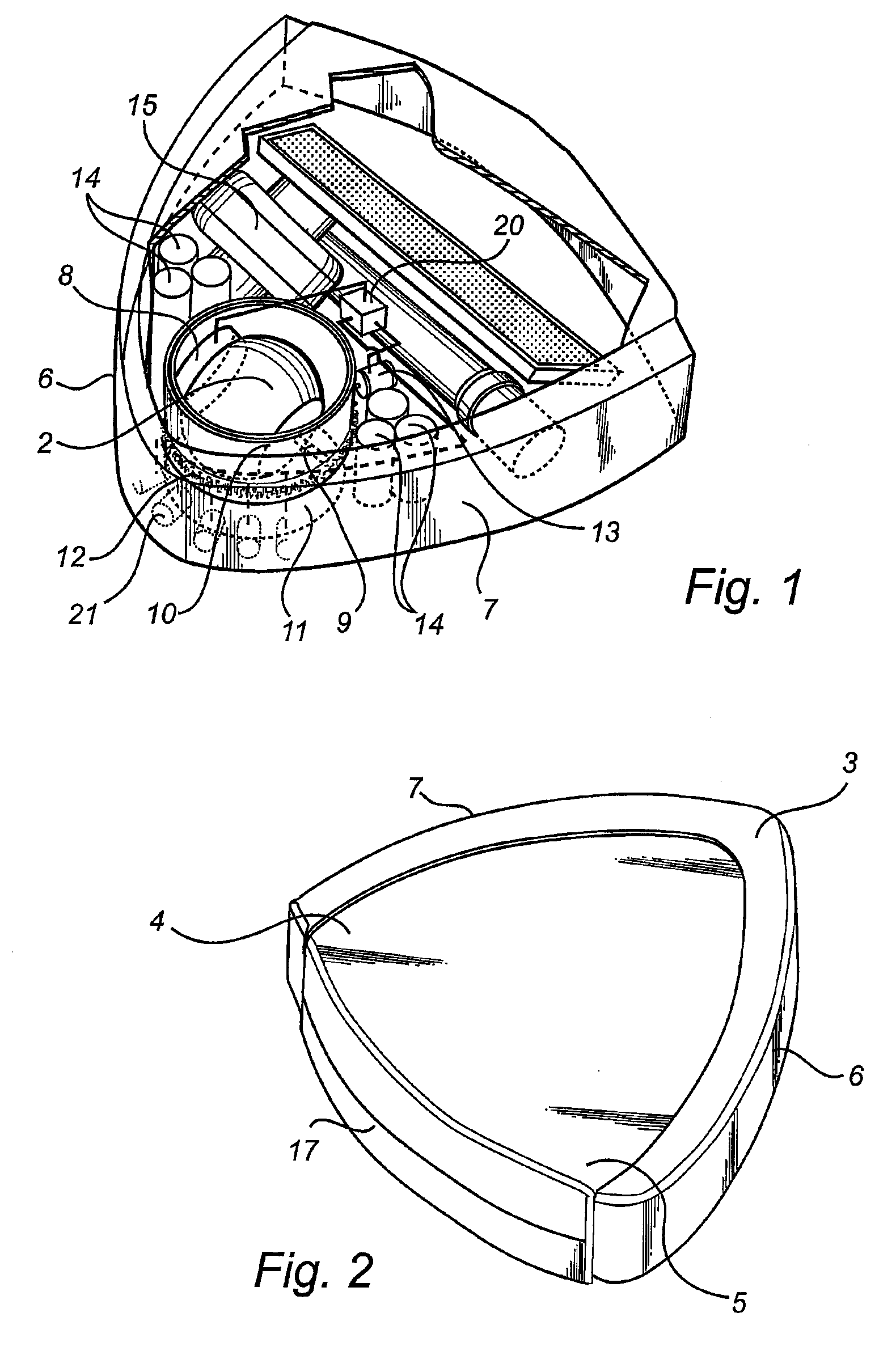
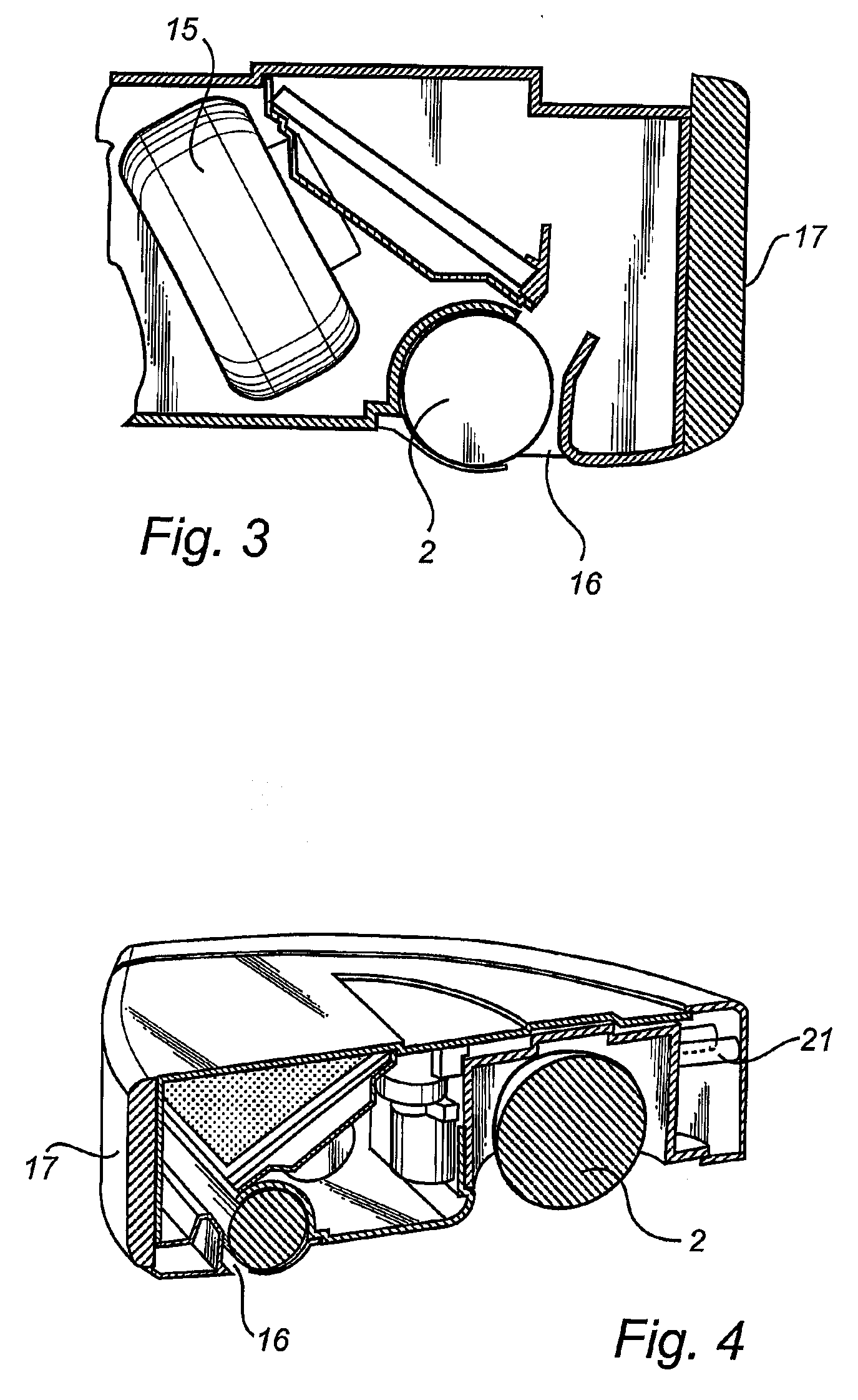
[0044]In FIGS. 1-4, an exemplary embodiment of the invention in the form of a robotic vacuum cleaner is shown. The vacuum cleaner comprises a main body 1 in the from of a housing. The main body has a general overall shape of an equilateral triangular block having a front end portion 3, a left rear end portion 4 and a right rear end portion 5. These three end portions 3, 4, 5 form three rounded corner portions. A left side wall 7 extends from the front end portion 3 to the left rear end portion 4, and a right side wall 6 extends from the front end portion 3 to the right rear end portion 5. The left and the right side walls 6, 7 form together a continuous bumper extending from the left rear end portion 4 to the right rear end portion 5 via the front end portion 3. The bumper is a flexible mounted part of the main body 1. Finally, a rear side wall 17 extends from the left rear end portion 4 to the right rear end portion 5.

[0045]The bumper cooperates with several sensors 21. The sensors...


PUM


Abstract

A robotic cleaning device having a main body with a controllable drive means to move the device over a surface, a cleaning means to clean the surface, an obstacle detecting means, and a control means connected to the drive means and the obstacle detecting means. The main body has a left wall connecting a front end portion with a left rear end portion and a right wall connecting the front end portion with a right rear end portion. The control means receives information from the obstacle detecting means about a detected obstacle and controls the drive means to rotate the device around a main left-turn axis at the left rear end portion or a main right-turn axis at the right rear end portion, such that the device turns one around one of the axes. The side walls are configured such that the device clears the obstacle by the turning motion.

Description

PRIORITY CLAIMS[0001]The present invention claims the benefit of Swedish Application No. 0501613-4 filed Jul. 8, 2005, and International Application PCT / SE2006 / 000847, filed Jul. 6, 2006 and published as International Publication No. WO 2007 / 008148 on Jan. 18, 2007. The foregoing references are incorporated herein in their entireties.TECHNICAL FIELD OF THE INVENTION[0002]The present invention relates to a robotic cleaning device, for example a robotic vacuum cleaner.BACKGROUND ART[0003]Robotic cleaning devices, such as robotic vacuum cleaners, are known in the state of the art. One such robotic cleaning device is disclosed in U.S. Pat. No. 5,369,347, which reference is incorporated herein. This known device comprises a housing having an overall shape of a circular block. For driving the device, the device is provided with one driving wheel and two support wheels, which support wheels are arranged at diametrical opposite sides of the device. For steering the device, the driving wheel...

Claims


Application Information

Patent Timeline
IPC IPC(8): A47L5/00B60W60/00G05D1/02
CPCA47L9/00A47L9/009A47L2201/04G05D1/0227G05D2201/0203A47L2201/00B60K7/0007B60K17/30B60K2007/0038B60K2007/0092A47L9/28A47L11/40
Inventor HAEGERMARCK, ANDERS
Owner AB ELECTROLUX
Learn More