Display apparatus and electronic device provided with the same

a technology of electronic devices and display apparatus, which is applied in the direction of instruments, computing, electric digital data processing, etc., can solve the problems of limited element configuration of optical sensors, and achieve the effect of strong resistance to electromagnetic nois

Inactive Publication Date: 2009-05-14
SHARP KK
View PDF9 Cites 21 Cited by
  • Summary
  • Abstract
  • Description
  • Claims
  • Application Information

AI Technical Summary

Benefits of technology

[0043]As described above, according to the present invention, a display apparatus having an environment sensor (e.g., an optical sensor) formed in a peripheral region of an active matrix substrate and an electronic device can be provided, in which the display apparatus uses a layer made of the same material as that of the interlayer insulation film (second interlayer insulation film) in a pixel array region as a surface protective film of the environment sensor, prevents the surface protective film from being denatured, and is strong to electromagnetic noise.

Problems solved by technology

On the other hand, in the case where an optical sensor for detecting the brightness of ambient light is formed monolithically in a peripheral region of a display apparatus with a TFT having the above configuration in a display region, if an attempt is made so as to minimize the increase in a production process, the element configuration of the optical sensor is limited.

Method used


Image

  • Display apparatus and electronic device provided with the same
  • Display apparatus and electronic device provided with the same
  • Display apparatus and electronic device provided with the same

Examples


first embodiment

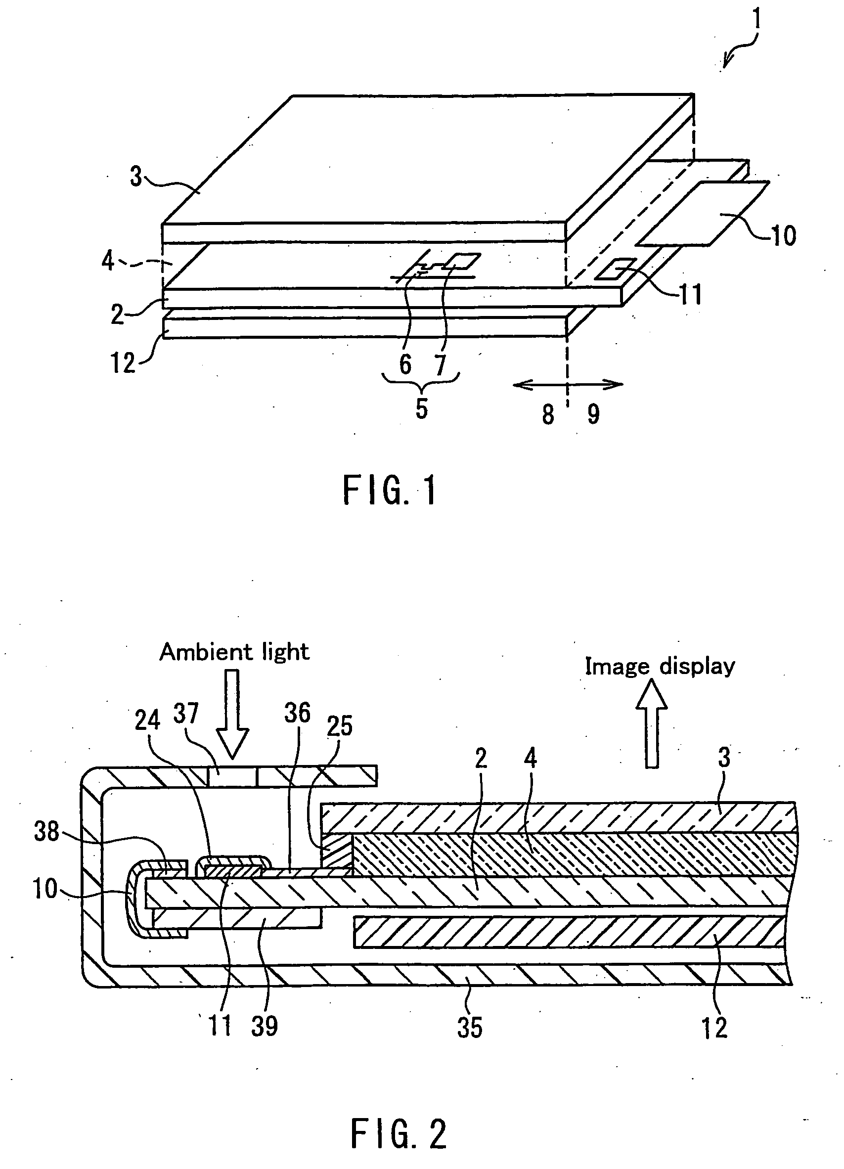
[0055]FIG. 1 is an entire configuration view of a display apparatus 1 according to one embodiment of the present invention. The display apparatus 1 includes an active matrix substrate 2 on which a number of pixels are arranged in a matrix, and a counter substrate 3 placed so as to be opposed to the active matrix substrate 2, and liquid crystal that is a display medium 4 is interposed in a gap between the substrates. The active matrix substrate 2 and the counter substrate 3 are bonded to each other with a frame-shaped seal resin (not shown) along an outer periphery of the counter substrate 3.

[0056]In each pixel 5 of the active matrix substrate 2, a thin film transistor (TFT) 6 and a pixel electrode 7 for driving the display medium 4 are formed. The counter substrate 3 is provided with a counter electrode (not shown) and a color filter (not shown).

[0057]The active matrix substrate 2 includes a region (pixel array region) 8 in which the pixels 5 are arranged, and a peripheral region 9 ...

second embodiment

[0095]FIG. 6 shows a schematic configuration of an electronic device according to one embodiment of the present invention. As shown in FIG. 6, an electronic device 60 according to the present embodiment includes the display apparatus 1 according to First Embodiment, and a control circuit 61 that controls the display brightness of the display apparatus 1 in accordance with the lightness information of ambient light detected by the optical sensor 11 of the display apparatus 1. In FIG. 6, the functional blocks in the display apparatus 1 and the electronic device 60 are abbreviated. The control circuit 61 may have a function of controlling any operation of the electronic device 60 in addition to the control of the display brightness. Furthermore, the electronic device 60 can have any functional blocks other than those shown in FIG. 6 depending upon the application thereof and the like.

[0096]The control circuit 61 controls the display brightness of the display apparatus 1 by adjusting th...


PUM


Abstract

In a display apparatus having an active matrix substrate, a counter substrate provided so as to be opposed to a pixel array region of the active matrix substrate, and a display medium provided in a gap between the active matrix substrate and the counter substrate, an optical sensor (11) is provided in a peripheral region of the pixel array region in the active matrix substrate. In order to make it difficult for the optical sensor (11) to change with time, and suppress the influence of electromagnetic noise on the optical sensor (11), in an upper layer of the optical sensor (11), a surface protective film (24) is formed of a transparent insulation layer (20a) made of the same material as that of an interlayer insulation film in the pixel array region and having an effect of attenuating a UV-light transmittance and a transparent conductive layer (7a) formed of the same material as that of the pixel electrode in an upper layer of the transparent insulation layer (20a).

Description

TECHNICAL FIELD[0001]The present invention relates to a flat panel type display apparatus such as a liquid crystal display apparatus and an electroluminescence (EL) display apparatus, and in particular, to a display apparatus having an environment sensor such as an optical sensor that detects the lightness of an ambient environment on an active matrix substrate. The present invention also relates to an electronic device provided with such a display apparatus.BACKGROUND ART[0002]A flat panel type display apparatus such as a liquid crystal display apparatus has currently been incorporated in a wide range of information devices, TV devices, and amusement devices, such as a mobile telephone, a PDA, a DVD player, a mobile game device, a notebook PC, a PC monitor, and a TV due to the features of thinness, light weight, and low power consumption, and further due to the technical development for the enhancement of display performance such as coloring, increase in definition, and support for...

Claims


Application Information

Patent Timeline
Patent Type & Authority Applications(United States)
IPC IPC(8): G09G5/00
CPCG02F1/13318G02F1/136227G02F2201/50G02F2201/086G02F2001/13312G02F1/13312
Inventor KATOH, HIROMINAGAI, TOMOYUKIIZUMI, YOSHIHIRO
Owner SHARP KK
Why Eureka
Try Eureka