
Carrier strip for nails or other securing elements

a carrier strip and nail technology, applied in the direction of nail, staples, containers, etc., can solve the problems of inability to accurately introduce and increase the manufacturing cost of the carrier strip, and achieve the effect of improving the adaptation of the nail or the securing element and greater manufacturing simplicity

Inactive Publication Date: 2009-05-14
COMPANIA NEUMATICA DE CALVADO
View PDF5 Cites 3 Cited by
  • Summary
  • Abstract
  • Description
  • Claims
  • Application Information

AI Technical Summary

Benefits of technology

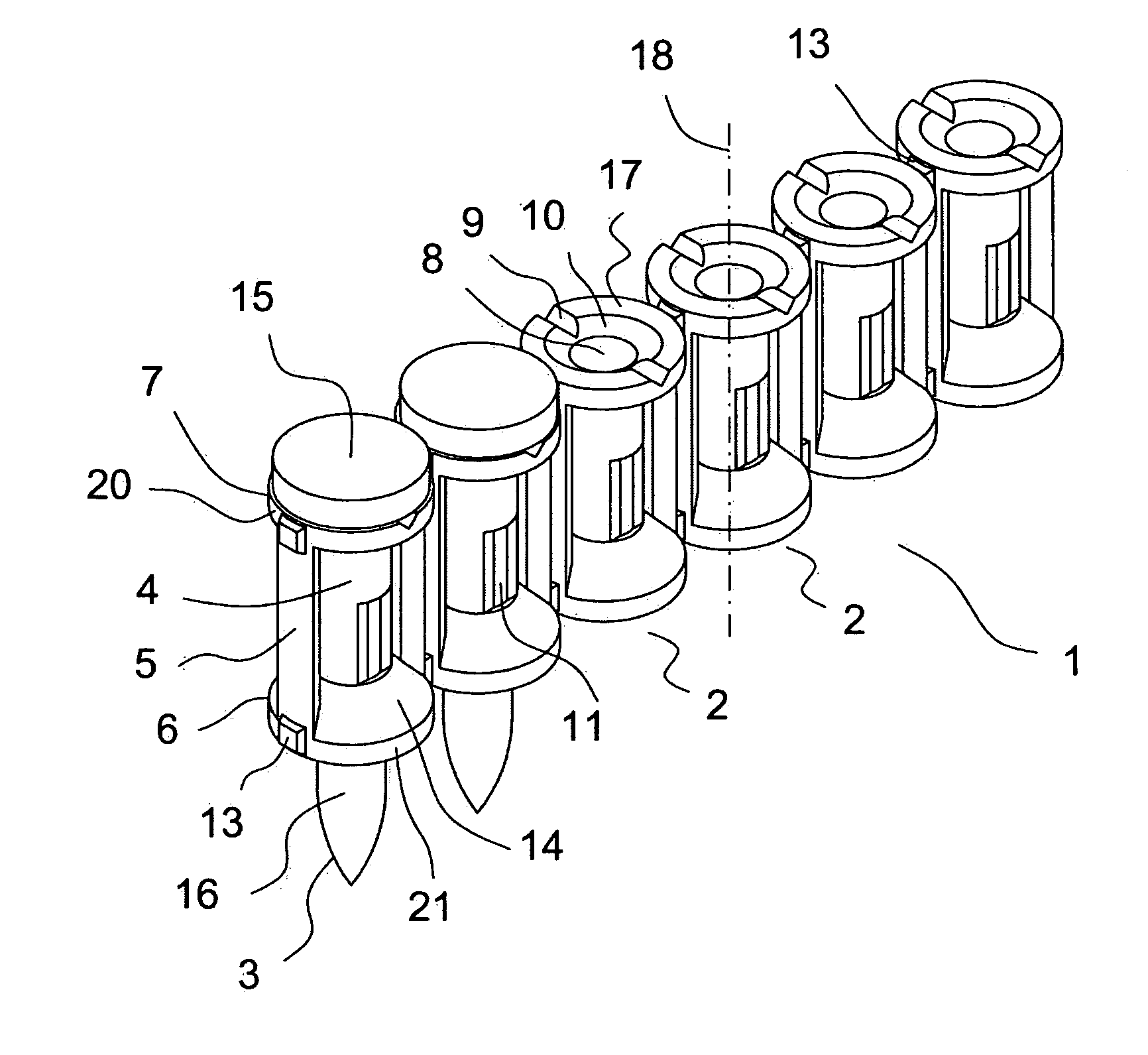
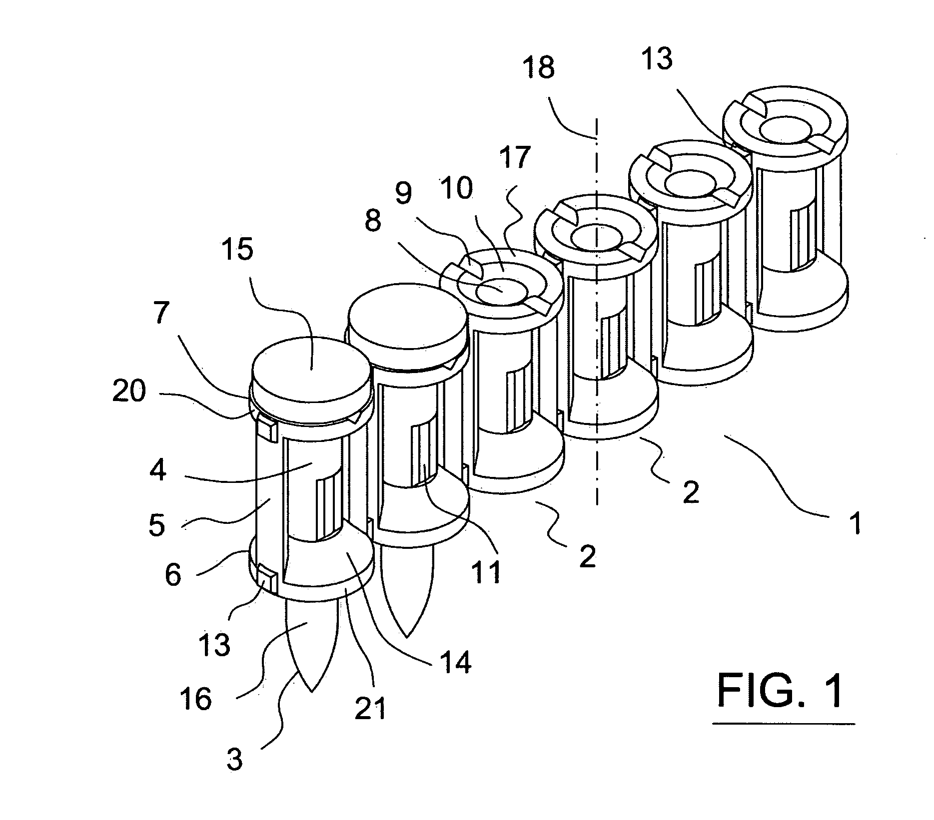
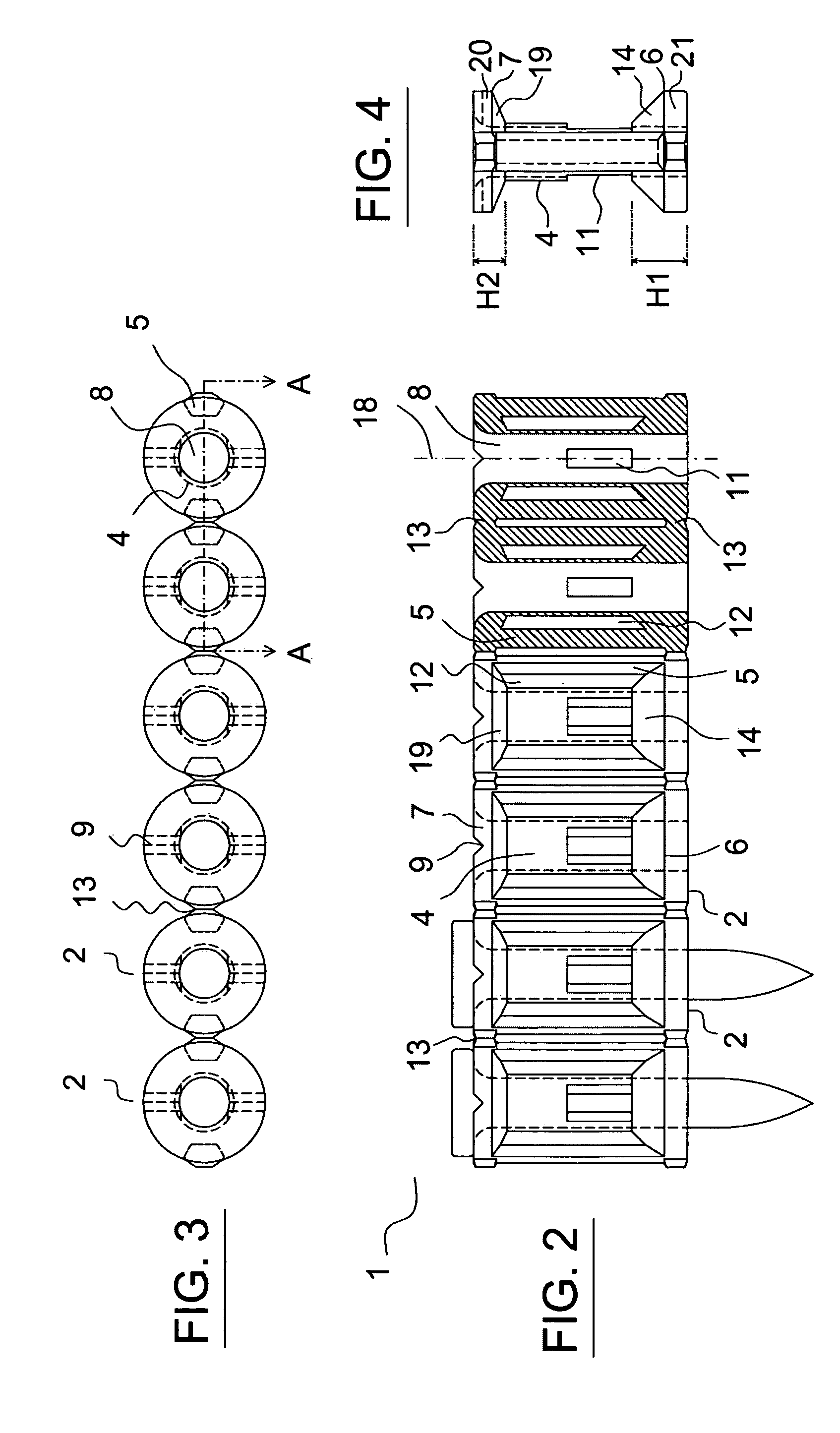
[0013]First of all, both the base and the crown are divided into a non-conical area, or cylindrical area, and a conical area, whereby the conical area is the closest to the central body, in such a way that the conical area serves as the transition area between the central body and the non-conical or cylindrical area of the crown or base. With this conical area, the manufacturing process is favoured and the breakage of the cartridge is simplified, as the cartridge has sections of a progressive size rather than brusque section changes.
[0014]Secondly, the height of the crown is lower than the height of the base, or in other words, the total height total of the non-conical and conical areas of the crown is greater than the total height total of the non-conical and conical areas of the base. It has been proven that using a larger base, the cartridge performance is improved in relation to the correct breakage of the crown combined with the correct operation of the base as a washer.
[0015]Additionally, the cartridge includes some lateral reinforcement pillars arranged parallel to the longitudinal axis of the cartridge and which connect the crown to the base, without coming into contact with the central body of the cartridge. In this way, through a single reinforcement element, the sturdiness of the crown and the base is improved, and hence the cartridge, without reinforcing its connection to the central body but rather by reinforcing its inter-connection. Furthermore, the lateral pillars reduce the amount of material used whilst maintaining the vertical rigidity of the cartridge and simplify the breakage of the cartridge, as in the latter case, they warp in the presence of increased pressure, and therefore provide a cleaner break.
[0016]The lateral pillars have a section almost in the shape of a trapezium. In this way, it is easier to turn out the cartridge during the manufacturing process, simplifying this process. Furthermore, given that the pressure on the cartridge is distributed by moments and therefore the effort is greater in the radially exterior area of the pillar than in the radially interior area of the pillar, the section in the shape of a trapezium distributes the material analogically to the distribution of effort, optimizing the performance of the material used.
[0017]On the other hand, in order to improve the positioning of the nail in the cartridge, the opening of the central passage gap to the external surface of the crown (surface which is closest to the head of the nail when it is introduced into the cartridge) is tapered. In this way, if the transition between the head and the tip of the nail is not right-angled but rather is curved or bevelled, an equally valid contact between the nail head and the external surface of the crown of the cartridge will be achieved.
[0018]In the central body of the cartridge, at least two windows or openings are made on a plane parallel to the longitudinal axis of the cartridge, whereby these windows are diametrically opposite with respect to the longitudinal axis, in such a way that they are opposite each other, giving the impression of a passage gap. The purpose of these windows is to simplify the breakage of the cartridge. Furthermore, the adjacent location to the base promotes the fact that the breakage of the cartridge ends at the base and this may be detached without breaking to operate as a washer.

Problems solved by technology

This reinforcement can be improved because although it provides appropriate vertical rigidity, it uses an excessive amount of material which increases the manufacturing cost of the carrier strip.
This system presents an important disadvantage: as there is no central body, there is no nail guide in the entire central area between rings and therefore as the nail advances, it may turn and hence fail to be introduced correctly in the cartridge during the assembly phase.

Method used


Image

  • Carrier strip for nails or other securing elements
  • Carrier strip for nails or other securing elements
  • Carrier strip for nails or other securing elements

Examples


Embodiment Construction

[0011]In order to achieve the aforementioned objectives, a carrier strip for nails (or other similar securing elements equipped with a head and point) is defined, in which the strip comprises a number of cartridges arranged in series and successively interlinked, each cartridge holding a nail or securing element. The cartridge mainly consists of a preferably cylindrical central body arranged around a central longitudinal axis, in which this central longitudinal axis is. perpendicular to the direction of the carrier strip. The central body is finished off on its upper side by a cover or crown and on its lower side by another cover or base, whereby the crown and the base are concentric to the central body and have a greater surface area. Both the crown and the central body and the base are crossed by a central passage gap, centred with respect to the longitudinal axis, and whose function is to hold the nail. To provide this function, the central passage gap has a diameter greater or e...


PUM


Abstract

A carrier strip (1) for nails (3) or other securing elements to feed an automatic nailing machine, which is characterized by a series of cartridges (2), whereby each cartridge (2) holds a nail (3). The cartridges (2) have a cylindrical central body (4) finished off at the ends by a wider base (6) and crown (7), with a special feature in which the transition between the central body (4) and the base (6) and crown (7) is carried out by conic geometry. Furthermore, the vertical reinforcement of the cartridge (2) is provided by two lateral pillars (5), parallel to the longitudinal axis (18) of the central body (4), which links the base (6) and the crown (7) without coming into contact with the central body (4).

Description

FIELD OF THE INVENTION[0001]The invention relates to a carrier strip for nails or other similar securing elements, for use in an automatic nailing machine into which nails are fed by means of a continuous nail carrier strip.PRIOR ART[0002]The operation of automatic nailing machines is based on the pressurized nailing or automatic release of nails or other securing elements, which are individually and progressively fed to the release area of the machine by means of a carrier strip for nails.[0003]In the prior art, numerous types of carrier strips for nails or other securing elements are known, ranging from the simplest flat strips which transport nails that cross the separated strip at a regular distance, to more complex strips consisting of a series of essentially cylindrical cartridges including more or less reinforcement elements, in which each cartridge holds a nail and is secured to the adjacent cartridges by certain securing devices.[0004]The release mechanism of the automatic ...

Claims


Application Information

Patent Timeline
Patent Type & Authority Applications(United States)
IPC IPC(8): B65D85/24
CPCF16B15/08B25C1/184
Inventor DEL HOYO, INAKI DIEZ
Owner COMPANIA NEUMATICA DE CALVADO
Learn More