
Rotating biopsy device and biopsy robot

a biopsy robot and rotating technology, applied in the field of rotating biopsy devices and biopsy robots, can solve the problems of bulky devices, pain, discomfort and inaccurate sampling, pain to patients, etc., and achieve the effect of convenient use by medical practitioners

Inactive Publication Date: 2009-04-30
KIM STANLEY I
View PDF30 Cites 117 Cited by
  • Summary
  • Abstract
  • Description
  • Claims
  • Application Information

AI Technical Summary

Benefits of technology

"The present invention provides a rotating biopsy device that is more comfortable for patients, easier for medical professionals to use, and yield more accurate sampling and excision of tissue for lab work or analysis. The device includes a cannula with a lumen and a rotational biopsy needle that can be axially and rotatably move within the cannula. The needle has at least one blade that can remove a tissue sample from the target site and hold it during retraction from the patient's body. The device can also include a locking mechanism to secure the position of the needle, a guide needle, a needle rotator, and a biopsy robot. The method of collecting a tissue sample includes inserting the cannula and advancing the rotational biopsy needle to the target site, rotating the needle to remove the sample, and retracting it out of the patient's body. The device and method can be used in the treatment of various target tissue sites."

Problems solved by technology

The Robopsy systems' mechanism for needle movement uses several different motors that can make the device bulky.
Although needle localization can be done by the computer and mechanical engineering system, it is still partially blind biopsy as the radiologist can not see the CT monitor when he or she has to obtain the sample tissue in the last moment of the biopsy procedure.
If the biopsy needles have the spring propulsion system, the doctor has to release the trigger, which can cause pain, discomfort and inaccurate sampling by pushing or shaking the biopsy needles and patient's body.
Frequently, the doctor has to pull out and reinsert the needle repeatedly, resulting in pain to the patient.
There are several problems in common core biopsy techniques.
First, when the cannula and inner biopsy needles are pushed forward to cut the tissue and are separated from the target lesion in cases in which the spring propelled biopsy device is used, often it causes a sudden jerky motion and noise that frightens the patient.
It can also cause pain and discomfort.
Second, the forced forward movement of the needle by the spring mechanism can push the needle too far forward to miss the target lesion.
This can result in inaccurate sampling that requires repeated biopsy procedures that increase the pain and complications associated with repeated biopsy procedures.
Third, when the doctor uses the CT scan as the imaging equipment, the biopsy is a blind biopsy rather than precise image guided procedure, thus often resulting in inaccurate sampling.
However, this technique is not for biopsy of deep seated target tissue inside the organ, but for the sampling of the tissue in the surface, such as uterine cervix.
The Kieturakis biopsy system is very complicated, and recovering the severed tissue specimen is often difficult.
If the tissue sample is cancerous tissue, cutting the tumor in multiple small pieces can potentially spread the cancer cells within the patient's body.
The device ports, lumens and holes may also be blocked if the tissue size is too big to be sucked out.
But it still is complicated to operate and recovering the tissue specimen can also be problematic.
In addition, the size of the tissue sample may not be large compared to the size of the needles because of multiple layers of the needles and the suction apparatus.
Furthermore, recovering the severed tissue is complicated and difficult as a suction system or fluid and gas injection is required.

Method used


Image

  • Rotating biopsy device and biopsy robot
  • Rotating biopsy device and biopsy robot
  • Rotating biopsy device and biopsy robot

Examples


Embodiment Construction

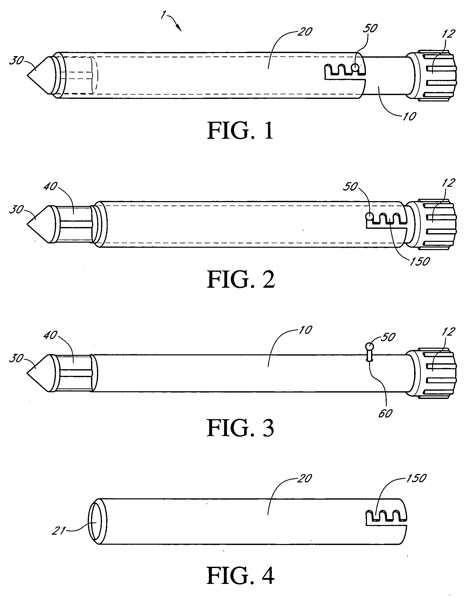
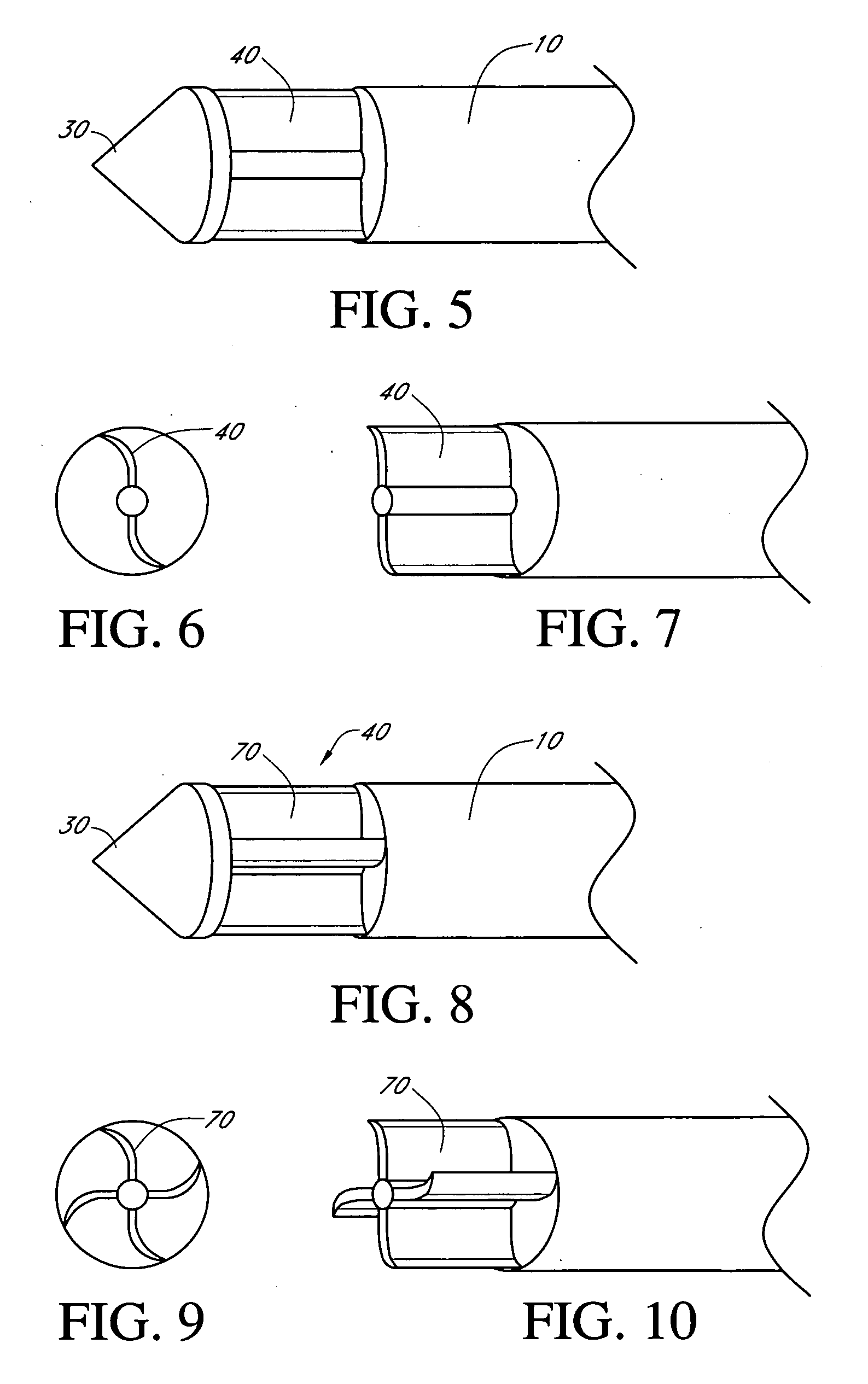
[0104]As should be understood in view of the following detailed description, this application is primarily directed to apparatuses, systems and methods for obtaining tissue samples. In one embodiment of the present invention, a rotatable biopsy needle with one or more biopsy blades can be used to effectively cut and obtain tissue samples. In one embodiment a rotating biopsy device with rotating blades cuts a tissue sample and utilizes centrifugal force to hold the tissue in place on the needle for extraction. In one embodiment, the rotating biopsy device uses electric powered automatic continuous rotation for easy recovery of the severed tissue samples. In some embodiments, continuous rotation generates centrifugal force that is very useful to keep the tissue sample in the blades until it is recovered. In one embodiment a total robotic biopsy with a rotating biopsy needle can be used with an automatic and / or remote control system to control localization, rotation of the blades and r...


PUM


Abstract

Embodiments of a needle biopsy device having a rotating needle mechanism to automatically cut sample tissue that can be operated remotely. A portable small biopsy robot can improve biopsy accuracy, reduce the pain and complications, and shorten the duration of the total biopsy time by using an automatic needle rotating mechanism and a needle localization system that allows a medical practitioner to perform the biopsy procedure from a remote distance. The needle biopsy device can include a cannula and a rotational biopsy needle with a blade the rotational biopsy needle axially and rotatably moveable within the cannula lumen, the blade configured to remove, cut, and / or separate a tissue sample from the target tissue site through rotation of the blade, and to hold the tissue sample in the rotational biopsy needle during proximal retraction from the patient.

Description

CROSS-REFERENCE TO RELATED APPLICATIONS[0001]This application claims the benefit of priority from U.S. Provisional No. 61 / 001,215 filed Oct. 31, 2007, which is incorporated in its entirety by reference, herein.BACKGROUND OF THE INVENTION[0002]1. Field of the Invention[0003]Various embodiments of the present inventions relate to devices and methods for tissue sampling or excision by means of a biopsy needle that cuts the sample tissue with a rotating movement.[0004]2. Description of the Related Art[0005]When an abnormal lesion such as malignant tumor is found inside an organ such as lung, liver, bone or breast in radiology images such as CT (Computer Tomography) scan, ultrasound scan or mammography, the abnormal lesion needs be sampled to determine its exact nature. Biopsy technique can be varied depending upon the location and the size of the abnormal lesion. In general it can involve a radiology doctor who introduces a needle into the target lesion by puncturing the outer skin whil...

Claims


Application Information

Patent Timeline
Patent Type & Authority Applications(United States)
IPC IPC(8): A61B10/02
CPCA61B10/0266A61B10/0275A61B19/2203A61B2017/3409A61B2010/0225A61B2017/3407A61B2019/223A61B2010/0208A61B34/30A61B34/35
Inventor KIM, STANLEY I.
Owner KIM STANLEY I
Learn More