
System for Measuring Electric Signals

a technology of electric signals and systems, applied in the field of measuring electric signals, can solve problems such as suspect data measured during the period of difference appearan

Inactive Publication Date: 2009-04-30
QUANTUM APPLIED SCI & RES
View PDF17 Cites 47 Cited by
  • Summary
  • Abstract
  • Description
  • Claims
  • Application Information

AI Technical Summary

Benefits of technology

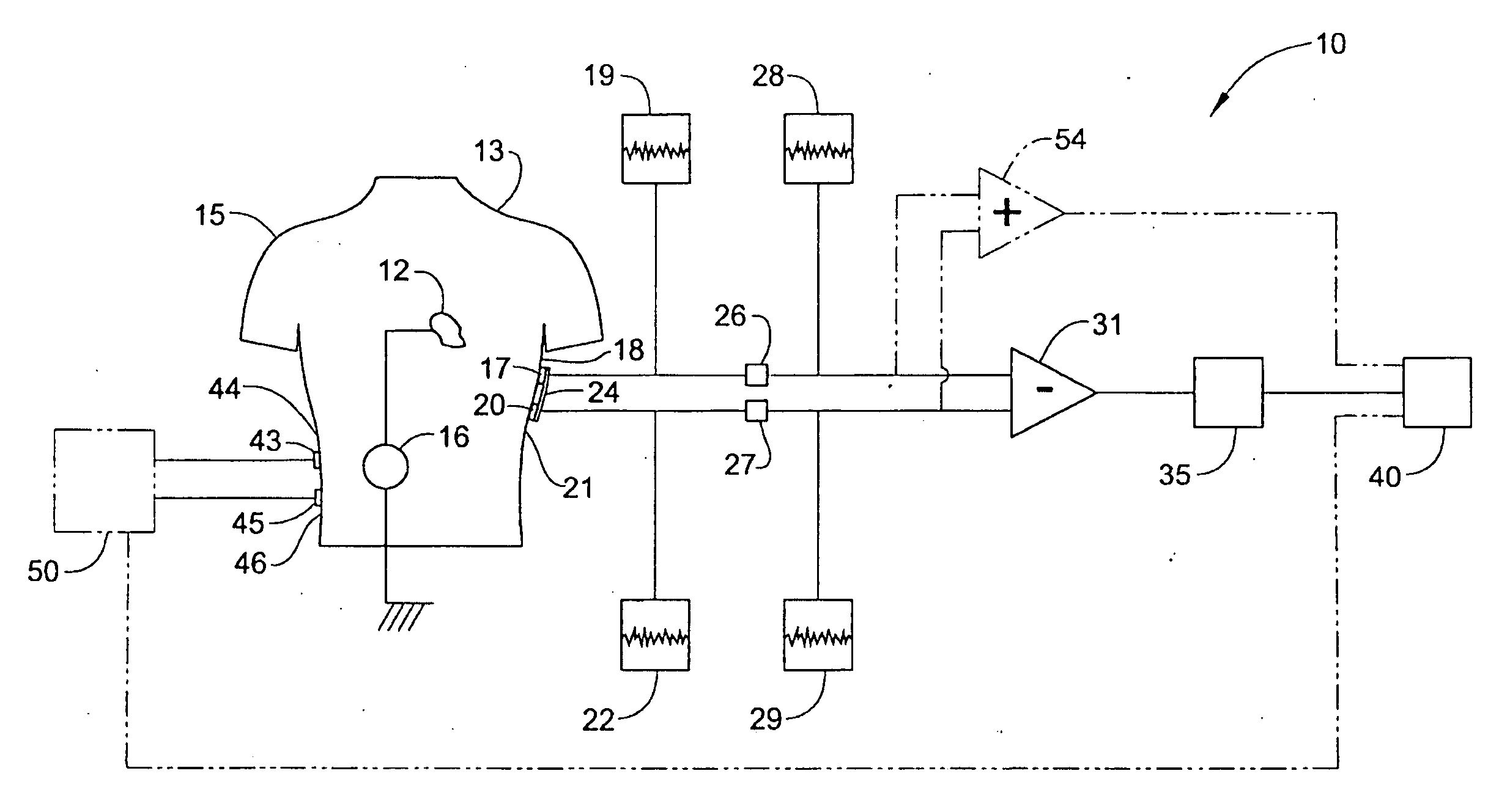
"The present invention is a system that can determine the validity of bioelectric data by using additional sensors that measure related signals. These sensors are placed at different locations in the body and can measure the electric potential of the heart or brain. The system predicts the expected signals based on the known characteristics of the sensors and the known relation between them and the primary source of the signals. If the observed signals do not show the expected relation, it concludes that a significant part of the measured signal must derive from a local source. The system compensates for changes in the sensors and filters the data to account for known changes in the source signal. The system can also use multiple sensors and adjust them to compensate for placement and electrical characteristics. The system measures electrical signals, adjusts them, and compares them to a threshold level to determine if the signals are caused by a local artifact or the distant source. The system can also use additional sensors and average the signals to obtain a more accurate final signal."

Problems solved by technology

If the difference is significant, then the data measured during the period in which the difference appears are suspect.

Method used


Image

  • System for Measuring Electric Signals
  • System for Measuring Electric Signals
  • System for Measuring Electric Signals

Examples


Embodiment Construction

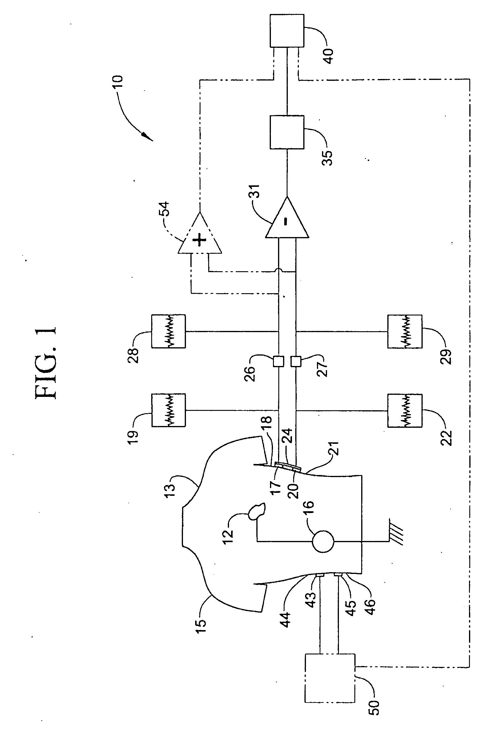
[0027]With initial reference to FIG. 1, a sensor system 10, constructed in accordance with the present invention, is arranged to measure signals from a bioelectric source 12 within a body 13 of an individual 15, such as a medical patient, animal, test subject or the like. Bioelectric source 12 creates an electric potential of interest 16 which is depicted as a cardiac signal, but could also be generated by other muscle, nerve or brain action. A first sensor 17 is placed at a first measurement location 18 so as to detect electric potential of interest 16 and generate a first electrical signal 19 possibly representative of electric potential of interest 16. Similarly a second sensor 20 placed at a second measurement location 21 near first sensor 17 so as to detect electrical potential of interest 16 and generate a second electrical signal 22 possibly representative of electric potential of interest 16. First and second sensors 17 and 20 are positioned near to each other and far enough...


PUM


Abstract

A system for determining if signals present at bioelectric sensors derive from an intended source or from different, localized sources or artifacts includes a first sensor placed to detect the electric potential of interest and generate a first electric signal possibly representative of the electric potential of interest and a second sensor placed near the first sensor and preferably a relatively large distance away from the source. The second sensor detects the electrical potential of interest and generates a second electrical signal which also possibly represents the electrical potential of interest. An electronic circuit determines whether a difference between the electrical signals exceeds a certain threshold, thus indicating that either one or both of the signals is a measure of an artifact and not the electric potential of interest.

Description

CROSS-REFERENCE TO RELATED APPLICATIONS[0001]The present application represents a National Stage application of pending PCT / US2007 / 009748 filed Apr. 23, 2007 entitled “System for Measuring Electric Signals”, and further claims the benefit of U.S. Provisional Patent Application Ser. No. 60 / 794,275 filed Apr. 21, 2006 entitled “ECG Monitoring System”.STATEMENT REGARDING FEDERALLY SPONSORED RESEARCH AND DEVELOPMENT[0002]The U.S. Government has a paid-up license in this invention and the right in limited circumstances to require the patent owner to license others on reasonable terms as provided for by the terms of Phase II SBIR Contract No. W31P4Q-04-C-R293 awarded by DARPA.BACKGROUND OF THE INVENTION[0003]1. Field of the Invention[0004]The present invention pertains to the art of measuring electric signals and, more particularly, to a system for measuring bioelectric signals that determines whether detected signals derive from a source of interest or result from an artifact or other un...

Claims


Application Information

Patent Timeline
Patent Type & Authority Applications(United States)
IPC IPC(8): A61B5/04A61B5/308A61B5/332
CPCA61B5/0428H04R29/00A61B5/6804A61B5/30A61B5/308
Inventor MATTHEWS, ROBERT
Owner QUANTUM APPLIED SCI & RES
Learn More