Image forming apparatus
a technology of forming apparatus and forming plate, which is applied in the direction of thin material handling, article separation, article delivery, etc., can solve the problems of sheet pb>0/b> jamming, and achieve the effect of smooth switching back conveyan
- Summary
- Abstract
- Description
- Claims
- Application Information
AI Technical Summary
Benefits of technology
Problems solved by technology
Method used
Image
Examples
first embodiment
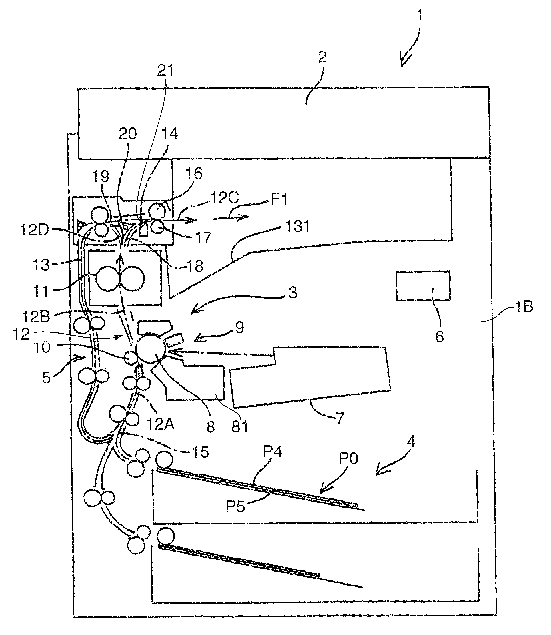
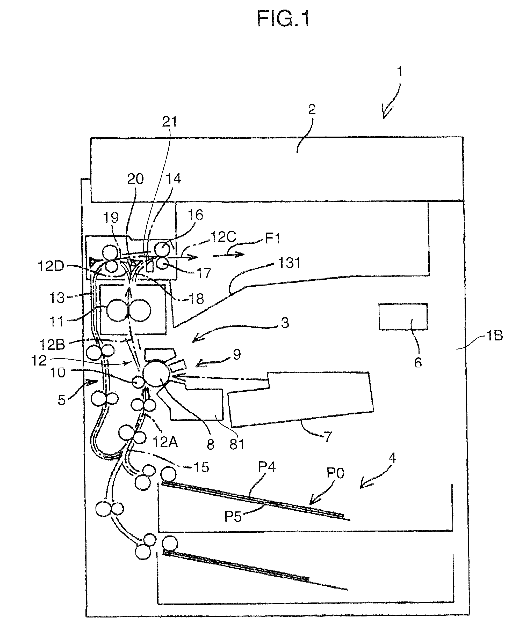
[0020]FIG. 1 is a front sectional view showing a schematic configuration of an image forming apparatus 1 in accordance with an embodiment of the present invention. The image forming apparatus 1 includes an apparatus main body 1B and a reading section 2 which is arranged on top of the apparatus main body 1B and optically reads a document image to be copied.
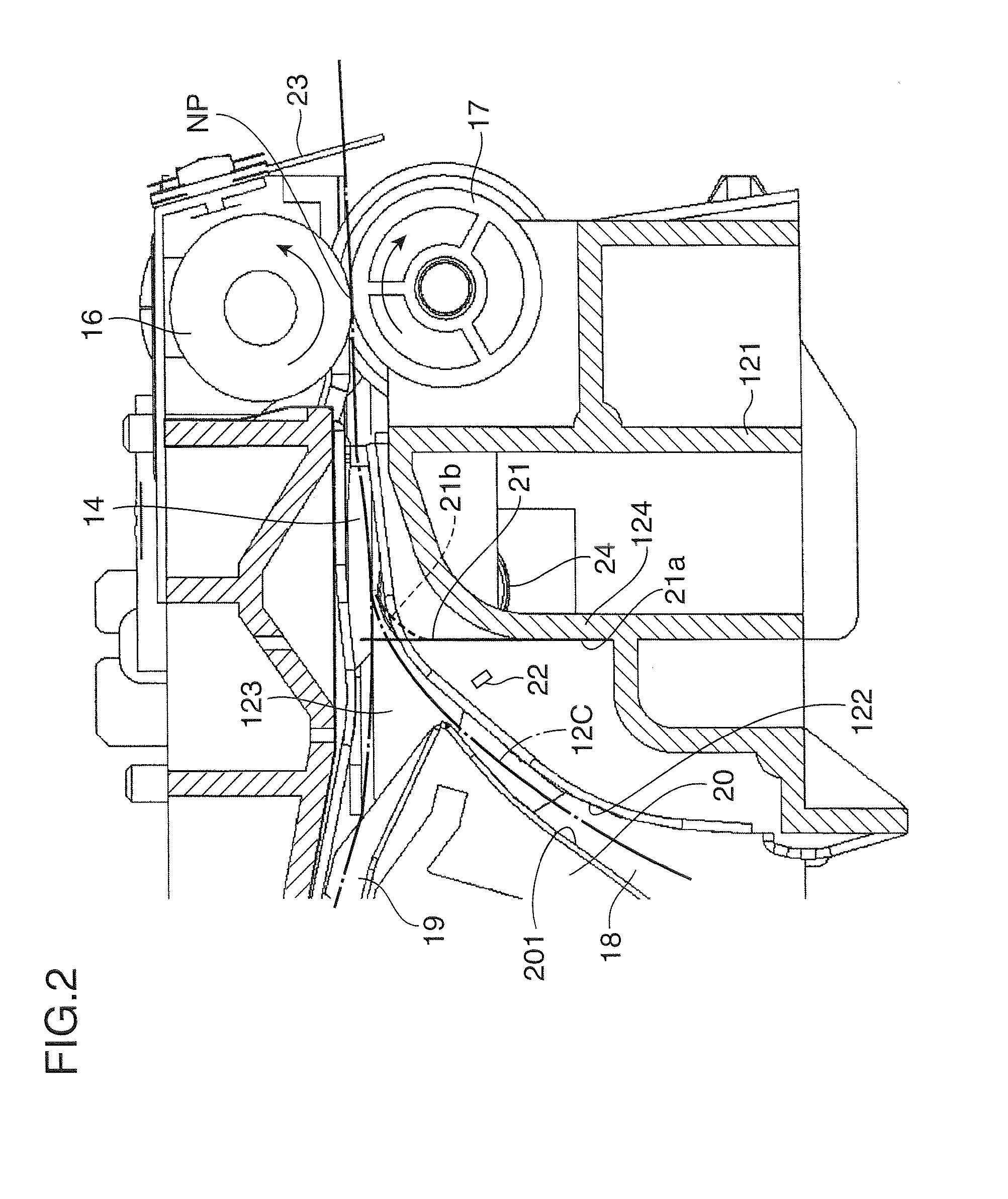
[0021]The apparatus main body 1B accommodates an image forming section 3 for forming an image onto a sheet P0 in accordance with image data of a document image which is obtained from the reading section 2, a sheet-supplying section 4 for supplying a sheet P0 to the image forming section 3, a sheet-conveying section 5 for conveying the sheet P0 to outside from the sheet-supplying section 4 through the image forming section 3, and a controller 6 that executes controlling operations of the above-described sections of the image forming apparatus 1. Between the reading section 2 and the apparatus main body 1B, there is provided a sheet-...
second embodiment
[0048]FIG. 5 is a sectional view of the peripheral portion of the sheet-discharging rollers 16 and 17 in accordance with a second embodiment of the present invention. FIG. 6 is a perspective view of the sheet-discharging rollers 16 and 17 viewed from the sheet-discharging side. FIG. 7 is an enlarged view showing a left side end portion of FIG. 6. In these drawings, portions which are the same as those shown in FIGS. 1-4 are identified by the same reference signs, and description regarding these parts will be omitted or simplified.
[0049]In the second embodiment, an example is shown in which second flexible members 25 are arranged on a downstream side of the sheet-discharging rollers 16 and 17 in the sheet convey direction (forward conveyance). The second flexible members 25 orients the widthwise opposite end portions of the sheet P0 toward a central portion by contacting with opposite end portions of the sheet P0 which is discharged from the sheet-discharging rollers 16 and 17 toward...
third embodiment
[0056]FIG. 8 is a sectional view of the peripheral portion of the sheet-discharging rollers 16 and 17 in accordance with a third embodiment of the present invention. In the third embodiment, the first flexible members 21 in accordance with the first embodiment and the second flexible members 25 in accordance with the second embodiment are provided.
[0057]Configurations, arrangements, and functions of the first flexible members 21 and the second flexible members 25 are the same as those described above. The first flexible members 21 are arranged on the upstream side of the sheet-discharging rollers 16 and 17. When the sheet P0 is switched back, the first flexible members 21 come in contact with the underside surface of the sheet P0 to allow the sheet P0 to move to the inlet portion 19 of the reversing conveying passage 13 in a substantially horizontal posture. The second flexible members 25 are arranged on the downstream of the sheet-discharging rollers 16 and 17, and come in contact ...
PUM
| Property | Measurement | Unit |
|---|---|---|
| flexible | aaaaa | aaaaa |
| flexibility | aaaaa | aaaaa |
| sheet-conveying direction | aaaaa | aaaaa |
Abstract
Description
Claims
Application Information
 - R&D
- Intellectual Property
- Life Sciences
- Materials
- Tech Scout
- Unparalleled Data Quality
- Higher Quality Content
- 60% Fewer Hallucinations
Browse by: Latest US Patents, China's latest patents, Technical Efficacy Thesaurus, Application Domain, Technology Topic, Popular Technical Reports.
© 2025 PatSnap. All rights reserved.Legal|Privacy policy|Modern Slavery Act Transparency Statement|Sitemap|About US| Contact US: help@patsnap.com


