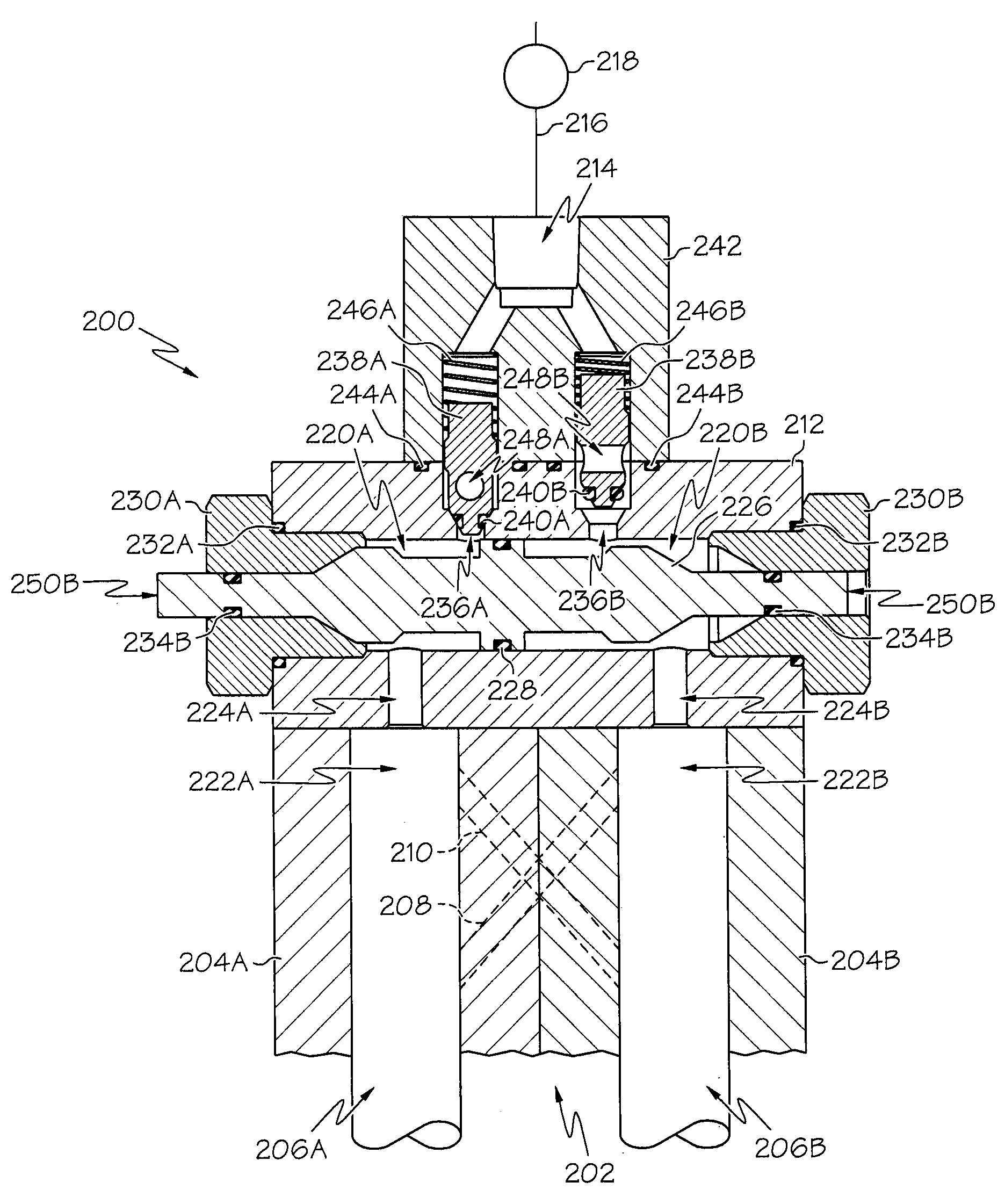
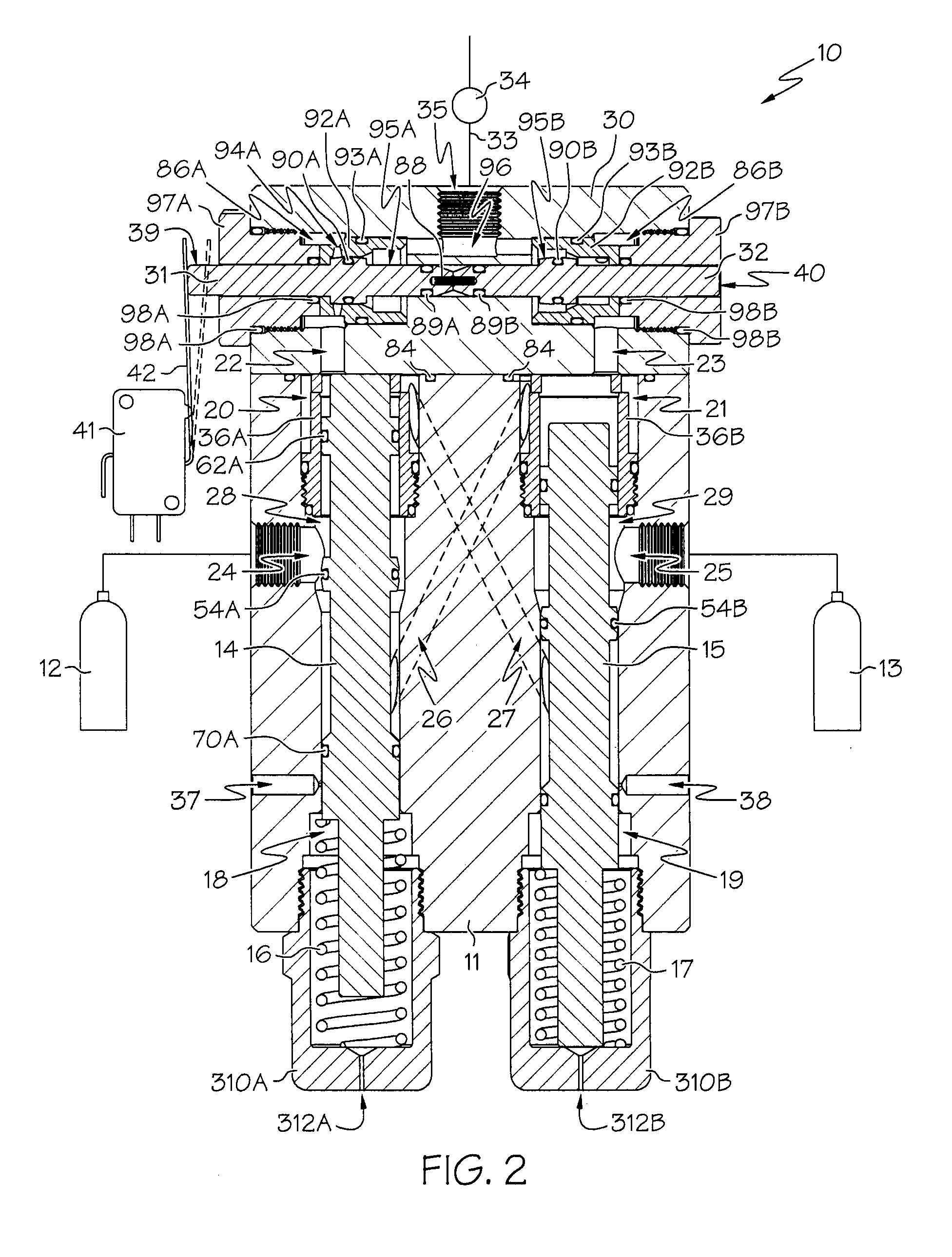
[0006]The following presents a simplified summary of the invention in order to provide a basic understanding of some example aspects of the invention. This summary is not an extensive overview of the invention. Moreover, this summary is not intended to identify critical elements of the invention nor delineate the scope of the invention. The sole purpose of the summary is to present some concepts of the invention in simplified form as a prelude to the more detailed description that is presented later.
[0007]In accordance with one aspect of the present invention, a valve for automatic switchover from a plurality of fluid pressure sources to a common outlet is provided. The valve includes a valve body including first and second inlet ports in fluid communication with first and second spool chambers, respectively. Each of said first and second inlet ports are adapted for fluid communication with respective fluid pressure sources, and each of said first and second spool chambers include an end chamber. The valve further includes first and second spools respectively in said first and second spool chambers and each including at least one sealing member carried thereon for selective sealing engagement with a portion of said first and second spool chambers, respectively. Each of said first and second spools are resiliently biased towards an open position, and fluid-biased towards a closed position. The valve further includes fluid passageways extending through said valve body receiving spool controlled fluid pressures and each terminating at the end chamber of said first and second spool chambers. In an open position, each of said first and second spools are adapted to provide delivery of pressurized fluid from an associated one of the inlet ports to the end chamber of the opposite spool chamber. In a closed position, each of said first and second spools are adapted via the at least one sealing member to inhibit delivery of pressurized fluid from an associated one of the inlet ports to the end chamber of the opposite spool chamber. The valve further includes a manifold assembly including at least one manifold bore in fluid communication with each of the end chambers and the common outlet. The manifold assembly includes first and second manifold spools moveable within said at least one manifold bore between open and closed positions for alternatively providing fluid communication between one of said end chambers and the common outlet while inhibiting fluid communication between the other of said end chambers and the common outlet.
[0008]In accordance with another aspect of the present invention, a valve is provided for automatic switchover from a plurality of fluid pressure sources to a common outlet. The valve includes a valve body including first and second inlet ports in fluid communication with first and second spool chambers, respectively. Each of said first and second inlet ports are adapted for fluid communication with respective fluid pressure sources, and each of said first and second spool chambers include a primary chamber, a secondary chamber, and an end chamber. The valve further includes first and second spools respectively in said first and second spool chambers and each including at least one sealing member carried thereon for selective sealing engagement with a portion of said first and second spool chambers to selectively inhibit fluid communication between said primary and secondary chambers, respectively. Each of said first and second spools are resiliently biased towards an open position wherein said primary chamber is in fluid communication with said secondary chamber, and fluid-biased towards a closed position wherein said primary chamber is inhibited from fluid communication with said secondary chamber via said at least one sealing member. The valve further includes fluid passageways extending through said valve body receiving spool controlled fluid pressures. The fluid passageways each begin at the secondary chamber one of said first and second spool chambers and terminate at the end chamber of the opposite spool chamber. In an open position, each of said first and second spools are adapted to provide delivery of pressurized fluid from an associated one of the inlet ports to the end chamber of the opposite spool chamber. In a closed position, each of said first and second spools are adapted via the at least one sealing member to inhibit delivery of pressurized fluid from an associated one of the inlet ports to the end chamber of the opposite spool chamber. The valve further includes a manifold assembly including at least one manifold bore in fluid communication with each of the end chambers and the common outlet. The manifold assembly includes first and second manifold spools moveable within said at least one manifold bore between open and closed positions for alternatively providing fluid communication between one of said end chambers and the common outlet while inhibiting fluid communication between the other of said end chambers and the common outlet.
[0009]In accordance with another aspect of the present invention, a valve is provided for automatic switchover from a plurality of fluid pressure sources to a common outlet. The valve includes a valve body including first and second inlet ports in fluid communication with first and second spool chambers, respectively. Each of said first and second inlet ports are adapted for fluid communication with respective fluid pressure sources, and each of said first and second spool chambers include a primary chamber, a secondary chamber, and an end chamber. The valve further includes first and second spools respectively in said first and second spool chambers and each including a plurality of sealing members carried thereon. At least one of the plurality of sealing members selectively inhibits fluid communication between said first chambers and said secondary chambers, and at least another of the plurality of sealing members selectively inhibits fluid communication between said primary chambers and said end chambers, respectively. Each of said first and second spools are resiliently biased towards an open position, and fluid-biased towards a closed position. The valve further includes fluid passageways receiving spool controlled fluid pressures, the fluid passageways each beginning at the secondary chamber one of said first and second spool chambers and terminating at the end chamber of the opposite spool chamber. In an open position, each of said first and second spools are adapted to provide delivery of pressurized fluid from an associated one of the inlet ports to the end chamber of the opposite spool chamber. In a closed position, each of said first and second spools are adapted via said at least one of the plurality of sealing members to inhibit delivery of pressurized fluid from an associated one of the inlet ports to the end chamber of the opposite spool chamber. The valve further includes a manifold assembly including at least one manifold bore in fluid communication with each of the end chambers and the common outlet. The manifold assembly includes at least one manifold spool moveable within said at least one manifold bore between open and closed positions for alternatively providing fluid communication between one of said end chambers and the common outlet while inhibiting fluid communication between the other of said end chambers and the common outlet.


