Mooring system

a floating structure and mooring grid technology, applied in the direction of anchoring arrangements, waterborne vessels, vessel construction, etc., can solve the problems of unfavorable mooring grid removal of all surface components, difficulty in restoring to the desired operation, and system elements remaining on the surface forming undesirable obstructions

Active Publication Date: 2009-04-30
FOBOKS AS
View PDF9 Cites 6 Cited by
  • Summary
  • Abstract
  • Description
  • Claims
  • Application Information

AI Technical Summary

Benefits of technology

[0021]In a yet further preferred embodiment of the mooring system according to the second aspect of the invention the artificial seafloor grid is arranged as one or more grid segments of substantially rectangular shape, where each grid segment is formed by four connected mooring grid members.

Problems solved by technology

It is limitation of all the above mentioned prior art solutions that even though a vessel may be connected to the mooring system in a removable fashion, all of the mooring structures rely on elements extending up to the surface of the sea, permanently situated at or near the surface of the sea when the mooring system has been positioned.
Hence this mooring grid does not allow for the removal of all surface components without loosing its form.
On the one hand, system elements remaining on the surface may form an undesirable obstruction.
On the other hand in a system where the surface elements are also removed, the mooring system changes shape and position, thereby making it difficult to restore to its desired operation.
If these surface floats were removed the anchoring system would fall to the bottom of the sea and be very hard to reinstall into its original shape.

Method used


Image

  • Mooring system
  • Mooring system
  • Mooring system

Examples


Embodiment Construction

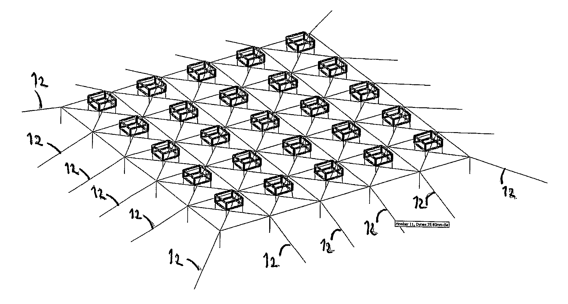
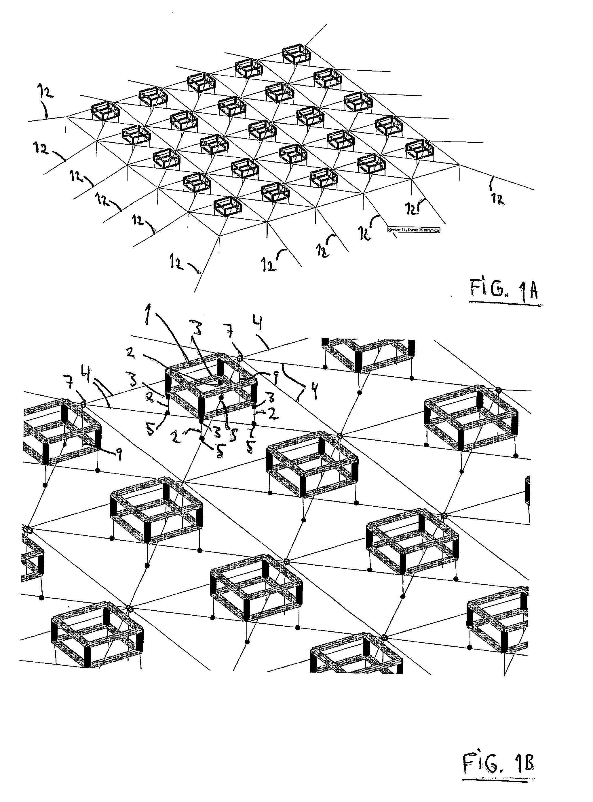
[0030]FIGS. 1A and 1B illustrate one embodiment of a mooring system according to the invention for mooring a surface or semi-submersible vessel or platform 1 at sea. In the context of this application the expression sea is intended to encompass ocean environments as well as inland saltwater or freshwater lake or fiord environments. FIG. 1A illustrate the complete assembly of mooring points in the mooring system, while FIG. 1B illustrates a section of the mooring system of FIG. 1A. Although the word platform will be used here, a platform may be equivalent to any floating structure, such as a vessel, a wave vessel, a rig or a rig station which is an autonomous structure or a part of a larger installation or structure installed at, or intended for, an offshore environment or location, for example in connection with the exploration of hydrocarbon reservoirs below the seabed, or in connection with any other similar activity in an aqueous environment, either at offshore or inland location...


PUM


Abstract

Mooring system arranged in a body of water for the mooring of multiple surface or semi-submersible vessels or platforms with a artificial seafloor grid designed as a mesh-like structure arranged in a substantially horizontal plane in the body of water. The artificial seafloor grid including means for attachment to said vessel or platform, and is mechanically coupled to the bottom of the sea using anchoring elements.

Description

FIELD OF THE INVENTION[0001]This invention relates generally to systems and methods for mooring floating structures such as floating vessels, platforms or rigs placed at sea.[0002]More particularly this invention relates to a mooring system for removable mooring of one or more rigs, platforms or other floating vessels as part of a larger installation at an offshore location.BACKGROUND OF THE INVENTION AND RELATED ART[0003]Mooring systems are known in the prior art. In WO 97 / 29943 a mooring system is described which includes a bridle having a star-like shape that is useful for mooring a single vessel or for mooring two or more vessels relative to one another. The mooring system describes in WO 97 / 29943 has a mooring bridle formed of a plurality of anchor connections spaced about a central mooring position. The system includes connecting lines attached to non-adjacent anchor buoys and attachable to the additional vessel and includes mooring lines attachable to the additional vessel ho...

Claims


Application Information

Patent Timeline
Patent Type & Authority Applications(United States)
IPC IPC(8): B63B21/00
CPCB63B21/50
Inventor OLGARDEN, HANSSTROMSEM, KARL CHRISTIANOLSEN, FRED
Owner FOBOKS AS
Why Eureka
Try Eureka