Linear digital phase interpolator and semi-digital delay locked loop (DLL)
- Summary
- Abstract
- Description
- Claims
- Application Information
AI Technical Summary
Benefits of technology
Problems solved by technology
Method used
Image
Examples
Embodiment Construction
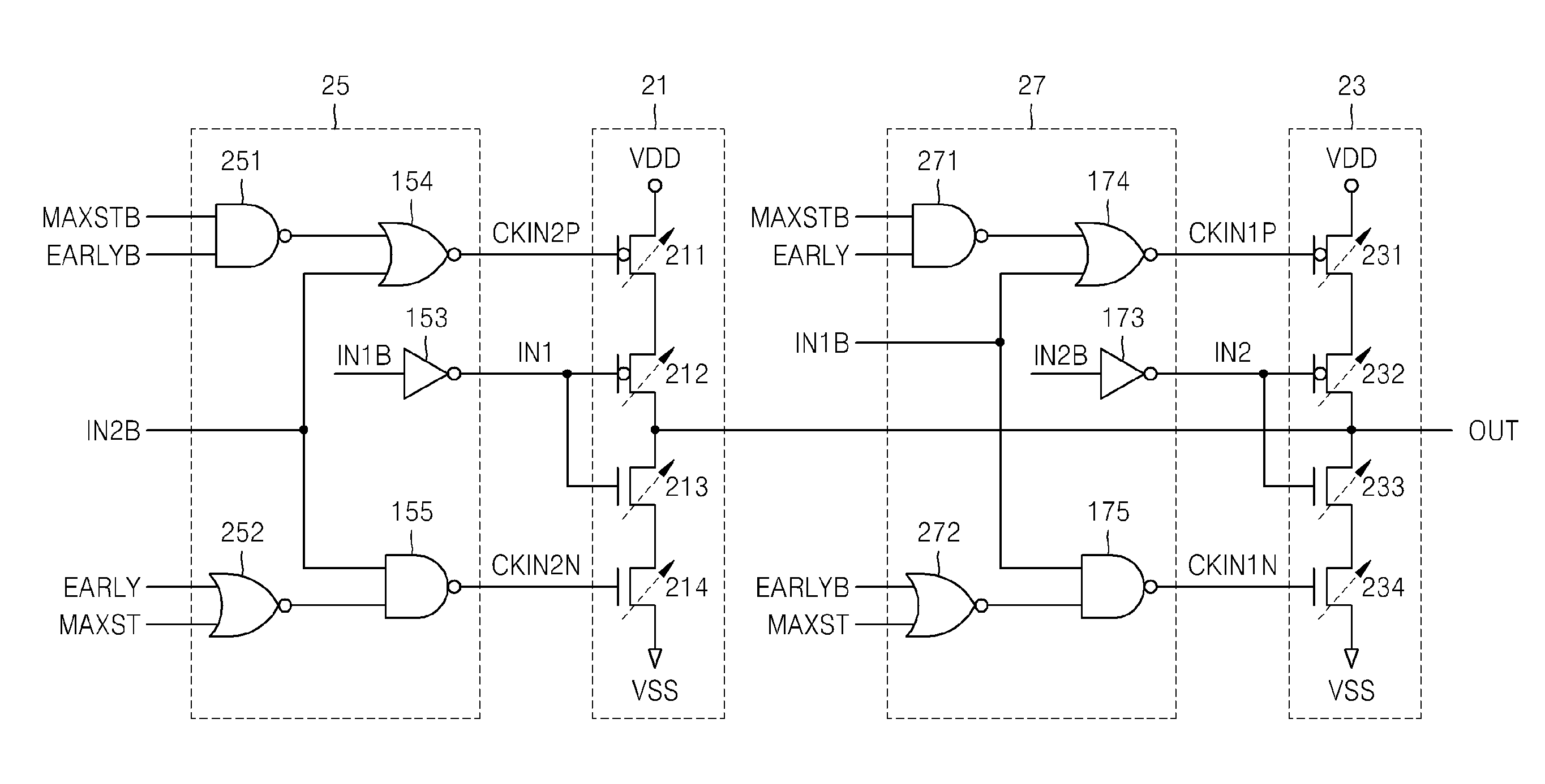
[0014]Hereinafter, embodiments of the present invention will be described with reference to the accompanying drawings. It should be noted, however, the invention may be variously embodied and is not limited to only the illustrated embodiments. Throughout the drawings and written description, like reference numerals and indicators are used to denote like or similar elements.
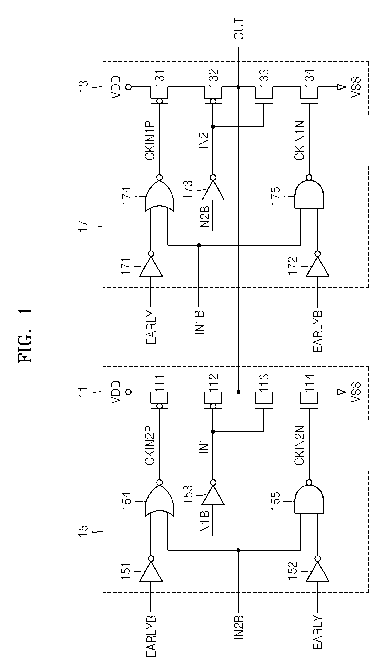
[0015]FIG. 1 is a circuit diagram illustrating a digital phase interpolator according to an embodiment of the present invention.
[0016]Referring to FIG. 1, the digital phase interpolator includes a first clocked inverter 11, a second clocked inverter 13, a first control circuit 15, and a second control circuit 17.
[0017]The first clocked inverter 11 and the second clocked inverter 13 are connected to a common output terminal OUT. The first clocked inverter 11 is controlled by a phase indicating signal EARLY and an inverted signal EARLYB thereof (actually controlled by clock signals CKIN2P and CKIN2N generated by the...
PUM
 Abstract
Description
Claims
Application Information
 - R&D
- Intellectual Property
- Life Sciences
- Materials
- Tech Scout
- Unparalleled Data Quality
- Higher Quality Content
- 60% Fewer Hallucinations
Browse by: Latest US Patents, China's latest patents, Technical Efficacy Thesaurus, Application Domain, Technology Topic, Popular Technical Reports.
© 2025 PatSnap. All rights reserved.Legal|Privacy policy|Modern Slavery Act Transparency Statement|Sitemap|About US| Contact US: help@patsnap.com


