
Steering control device and electrically powered vehicle

Active Publication Date: 2009-04-09
TOYOTA JIDOSHA KK +1
View PDF27 Cites 36 Cited by
  • Summary
  • Abstract
  • Description
  • Claims
  • Application Information

AI Technical Summary

Benefits of technology

[0007]In addition, another object of the present invention is to provide an electrically powered vehicle capable of ensuring a steering function if an already-existing steering apparatus fails.
[0010]Therefore, according to the steering control device in the present invention, even when the steering apparatus fails, the steering function can be ensured. Consequently, reliability of the steering system is improved.
[0013]Therefore, according to the steering control device, while enjoying advantages of the steer-by-wire system such as improvement in a degree of freedom in steering layout or a smaller size of the steering apparatus, reliability of the steering system can be improved.
[0017]Therefore, according to the electrically powered vehicle in the present invention, even when the steering apparatus fails, the steering function can be ensured. Consequently, reliability of the vehicle is improved.
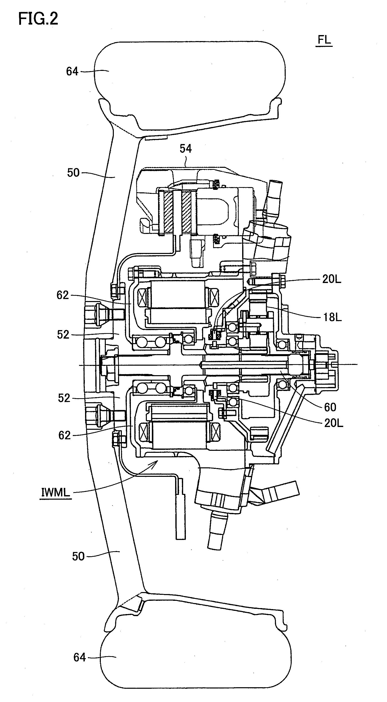
[0019]In the electrically powered vehicle, each of the first and second motors is implemented by what is called an in-wheel motor provided within a wheel of the front wheel. Therefore, according to the electrically powered vehicle, while enjoying various advantages as the in-wheel motor, such as effective use of a space that has conventionally been occupied by a drive system (such as a transmission or a differential gear), reliability of the vehicle can be improved.
[0020]As described above, according to the present invention, if the steering apparatus providing the steering angle to the front wheels fails, the torque difference in accordance with the operation angle of the steering wheel is produced in the output torque of the first and second motors for torque steer control. Therefore, even if the steering apparatus fails, the steering function can be ensured. Accordingly, even if the already-existing steering apparatus fails, the vehicle can continue to run.

Problems solved by technology

Namely, if the steering apparatus fails, the vehicle can no longer run.
In particular in a steering apparatus adopting a steer-by-wire system that has attracted attention in recent years, as the steering wheel and the front wheels are mechanically separate, improvement in reliability of the steering system is an important issue.

Method used


Image

  • Steering control device and electrically powered vehicle
  • Steering control device and electrically powered vehicle
  • Steering control device and electrically powered vehicle

Examples


Embodiment Construction

[0024]An embodiment of the present invention will be described hereinafter in detail with reference to the drawings. In the drawings, the same or corresponding elements have the same reference characters allotted, and detailed description thereof will not be repeated.

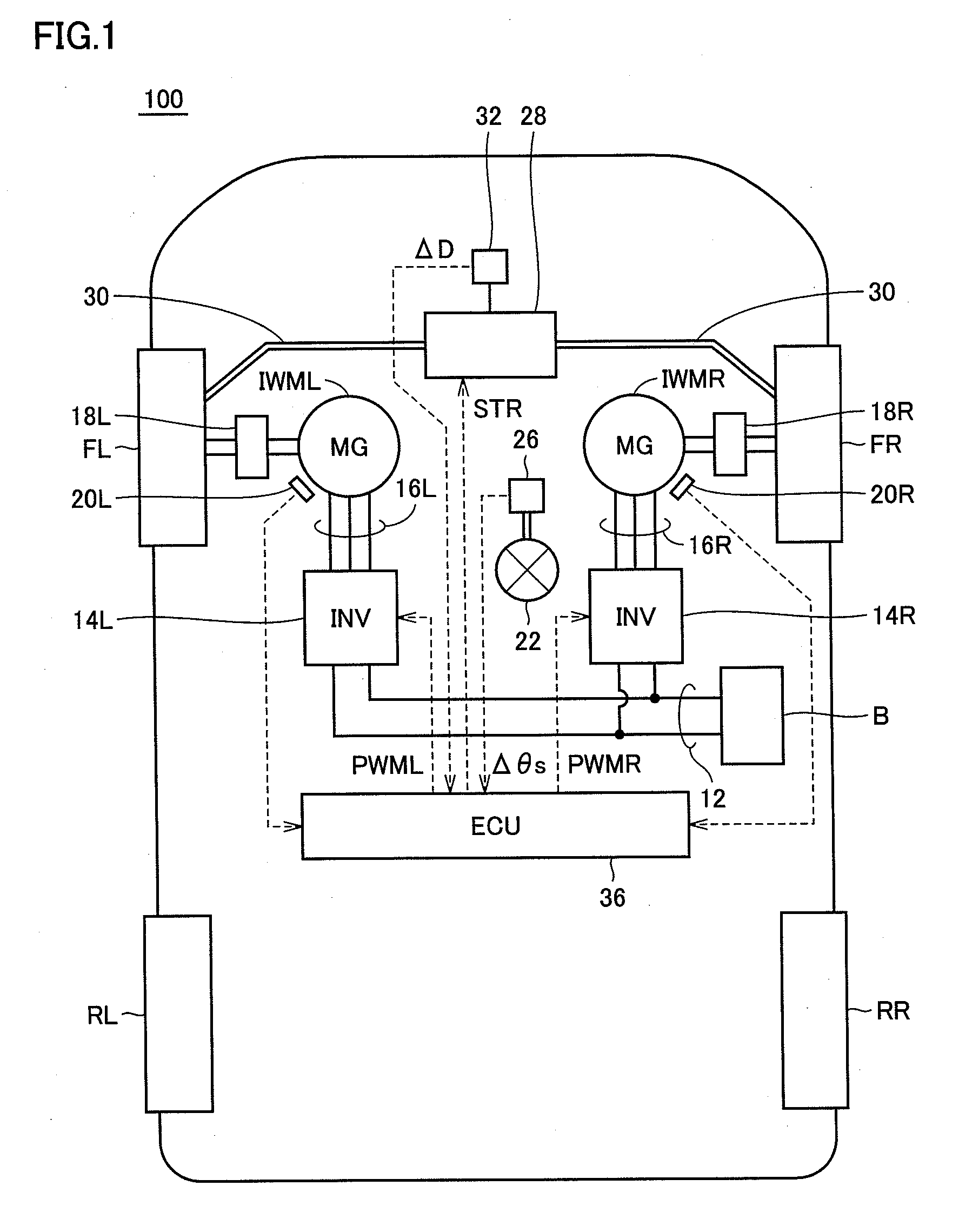
[0025]FIG. 1 is a functional block diagram showing an overall configuration of an electrically powered vehicle according to an embodiment of the present invention. Referring to FIG. 1, an electrically powered vehicle 100 includes a power storage apparatus B, a power supply cable 12, inverters 14R, 14L, three-phase cables 16R, 16L, motor-generators IWMR, IWML, reduction gears 18R, 18L, front wheels FR, FL, rear wheels RR, RL, and rotation sensors 20R, 20L. In addition, electrically powered vehicle 100 further includes a steering wheel 22, a steering wheel angle sensor 26, a steering actuator 28, a tie rod 30, a steering angle sensor 32, and an electronic control unit (hereinafter also referred to as “ECU”) 36.

[0026]Power...


PUM


Abstract

Motor-generators are incorporated in front wheels and drive the front wheels, respectively. An ECU determines whether or not a steering apparatus including a steering actuator, a tie rod and a steering angle sensor has failed, based on an operation angle of a steering wheel from a steering wheel angle sensor and a steering angle of the front wheels from the steering angle sensor. When the ECU determines that the steering apparatus has failed, the ECU provides torque difference for a torque instruction for the motor-generators in accordance with the operation angle of the steering wheel.

Description

TECHNICAL FIELD[0001]The present invention relates to a steering control device and an electrically powered vehicle, and more particularly to a steering control technique for an electrically powered vehicle in which left and right front wheels are driven with separate motors respectively.BACKGROUND ART[0002]Japanese Patent Laying-Open No. 9-117016 discloses an electric vehicle in which left and right front wheels are driven with separate motors respectively. In the electric vehicle, the left and right front wheels are driven with separate motors respectively and torque distribution between left and right motors is varied based on steering of a steering wheel.[0003]According to the electric vehicle, as an effect equivalent to that of power steering can be obtained by varying torque distribution between the left and right motors, the need for a power steering system can be obviated.[0004]On the other hand, Japanese Patent Laying-Open No. 9-117016 does not consider measures against fai...

Claims


Application Information

Patent Timeline
IPC IPC(8): B62D6/00B60K7/00
CPCB60K7/0007B60K17/046B60K2007/0038B60K2007/0092B60L3/0092Y02T10/7275B60L2220/44B62D5/003B62D9/002B62D9/005B60L15/2036Y02T10/64Y02T10/72
Inventor MIZUTANI, RYOJITSUCHIDA, MICHITAKATAHARA, YASUAKITOJIMA, YUKIISOGAI, SHIGETAKA
Owner TOYOTA JIDOSHA KK
Learn More