Eureka AIR delivers breakthrough ideas for toughest innovation challenges, trusted by R&D personnel around the world.

Tool tracking systems and methods for image guided surgery

a tool tracking and image-guided surgery technology, applied in the field of robots and robotic tools or instruments, can solve the problems of insufficient accurate position and orientation information for minimally invasive surgery, optical devices that interfere with endoscopic surgical procedures, and often obscure tissue or organs of interest in surgical cavities from view, so as to enhance the performance of the state space model

Active Publication Date: 2009-04-02
INTUITIVE SURGICAL OPERATIONS INC
View PDF59 Cites 388 Cited by
  • Summary
  • Abstract
  • Description
  • Claims
  • Application Information

AI Technical Summary

Benefits of technology

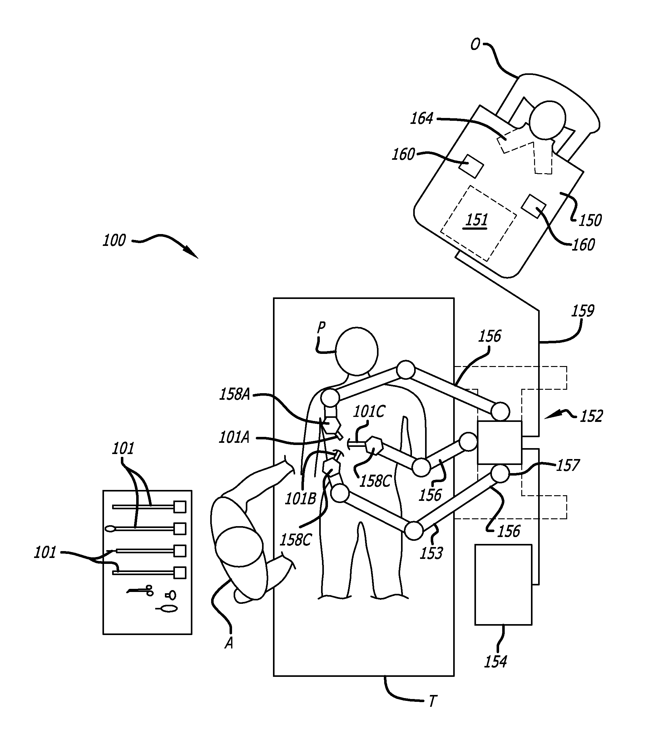
[0024]FIGS. 12C-12E are charts illustrating various view geometry statistics that may be used to enhance the performance of the state space model for adaptively fusing information sources together.
[0025]FIGS. 13A-13B are diagrams illustrating sequence matching of a feature in a sequence of one or more images from different sources.

Problems solved by technology

However if the robotic surgical tool is not in the field of view of the camera or it is otherwise hidden by tissue or other surgical tools, a surgeon may be left guessing how to move the robotic surgical tool when it is obscured from his view.
Moreover, tissue or organs of interest in a surgical cavity are often obscured from view.
However, optical devices can interfere with endoscopic surgical procedures and may not provide sufficiently accurate position and orientation information for a minimally invasive surgical system.
However, robotic surgical tools are often formed of metal and a magnetic device may not work well due to the interference generated by the movement of metal-tools and electrical motors in a minimally invasive surgical system.
Moreover, these may provide only a single clue of the position of a robotic surgical tool.

Method used


Image

  • Tool tracking systems and methods for image guided surgery
  • Tool tracking systems and methods for image guided surgery
  • Tool tracking systems and methods for image guided surgery

Examples


Embodiment Construction

[0030]In the following detailed description of the embodiments of the invention, numerous specific details are set forth in order to provide a thorough understanding of the present invention. However, it will be obvious to one skilled in the art that the embodiments of the invention may be practiced without these specific details. In other instances well known methods, procedures, components, and circuits have not been described in detail so as not to unnecessarily obscure aspects of the embodiments of the invention.

Introduction

[0031]Aspects of the invention include methods, apparatus and integrated systems for tool acquisition (locating) and tool tracking (kinematics-tracking (pose predicting) and full-tracking) of robotic medical tools. The method / system for tool tracking systematically and efficiently integrates robot kinematics and visual information to obtain pose (position / orientation) information, which can be used to obtain a more accurate pose of a robotic surgical tool tha...


PUM


Abstract

In one embodiment of the invention, a tool tracking system is disclosed including a computer usable medium having computer readable program code to receive images of video frames from at least one camera and to perform image matching of a robotic instrument to determine video pose information of the robotic instrument within the images. The tool tracking system further includes computer readable program code to provide a state-space model of a sequence of states of corrected kinematics information for accurate pose information of the robotic instrument. The state-space model receives raw kinematics information of mechanical pose information and adaptively fuses the mechanical pose information and the video pose information together to generate the sequence of states of the corrected kinematics information for the robotic instrument. Additionally disclosed are methods for image guided surgery.

Description

FIELD[0001]The embodiments of the invention relate generally to robots and robotic tools or instruments. More particularly, the embodiments of the invention relate to the acquisition and tracking of the position and orientation of robotic tools or instruments.BACKGROUND[0002]Minimally invasive surgical (MIS) procedures have become more common using robotic (e.g., telerobotic) surgical systems. An endoscopic camera is typically used to provide images to a surgeon of the surgical cavity so that the surgeon can manipulate robotic surgical tools therein. However if the robotic surgical tool is not in the field of view of the camera or it is otherwise hidden by tissue or other surgical tools, a surgeon may be left guessing how to move the robotic surgical tool when it is obscured from his view.[0003]Moreover, tissue or organs of interest in a surgical cavity are often obscured from view. A surgeon may have to initially guess the location of an organ of interest within a surgical cavity a...

Claims


Application Information

Patent Timeline
Patent Type & Authority Applications(United States)
IPC IPC(8): A61B19/00A61B1/04G06F19/00G16H20/40G16H30/40G16H40/67
CPCB25J9/1689G06K9/00624A61B1/018A61B1/04A61B1/3132A61B19/2203A61B19/5212A61B19/5244A61B2019/2223A61B2019/461A61B2019/5265A61B2019/5289A61B2019/5483G06F19/3418G06F19/3481G06K9/3241G06K2209/057G06T7/2033G06T2207/10021G06T2207/10068G06T2207/30004G06T2207/30241G09B23/28A61B5/061A61B5/1076A61B1/00193A61B2090/3983A61B34/20A61B2090/364A61B90/361A61B34/30A61B34/37A61B2090/061A61B2034/2065G06T7/246G16H20/40G16H30/40G16H40/67G06V10/255G06V2201/034A61B1/00194B25J15/0019B25J9/1656B25J13/089
Inventor ZHAO, WENYIHASSER, CHRISTOPHER J.NOWLIN, WILLIAM C.HOFFMAN, BRIAN D.
Owner INTUITIVE SURGICAL OPERATIONS INC
Why Eureka
Eureka Blog
Learn More