
Foil container with foil bag chambers which are arranged next to one another

a technology of foil bags and foil containers, applied in the field of foil containers, can solve the problems of high ejection force required for dispensing, and achieve the effect of reducing ejection for

Active Publication Date: 2009-04-02
HILTI AG
View PDF15 Cites 18 Cited by
  • Summary
  • Abstract
  • Description
  • Claims
  • Application Information

AI Technical Summary

Benefits of technology

[0010]The at least one additional outlet opening is arranged in the clear cross-section of the first outlet opening. The first outlet opening has a wall facing inward which defines the clear cross-section of the first outlet opening. The at least one additional outlet opening is arranged at a distance from the wall of the first outlet opening and is accordingly surrounded, advantageously completely, by the first outlet opening. Since one of the compound components is fed to the mixing element in the mixer housing within the at least one other compound component, all of the mixing steps of the mixing element which are adjacent to the outlet openings are completely wrapped around each other. This ensures a maximum possible blending of the compound components, so that the compound, which exits from the mixer housing, is mixed to the required degree over the entire process of squeezing the foil container.
[0011]When the mixing element is not radially symmetrical, a compound component can no longer flow past one of the wall portions of the mixing element at the start of the mixing process, depending on the position of the mixing element in the mixer housing, as was possible with a side-by-side feed. Irregular mixing results or variations in the extent of mixing of the compound components over the course of the ejection process are eliminated by the feeding process according to the invention. Since it is ensured that the compound components are thoroughly mixed with one another to a degree that can be reliably predetermined, fewer mixing steps are required for a correct blending of the compound components, and the mixing element can therefore be constructed so as to be shorter. Because of the shorter mixing path, smaller forces are sufficient for squeezing out the foil container, which makes it possible to use simple and inexpensive ejection devices.
[0014]The head is advantageously made of plastic in an injection-molding process. Due to the fact that the at least one additional outlet opening is arranged in the first outlet opening, the manufacture-dependent geometric warping that occurs in a side-by-side feed with a separating web, is eliminated when ejecting from the mold. Apart from a simpler ejection from the mold, the sealing of the mixer connection with the head is also improved by the simpler geometry of the head.
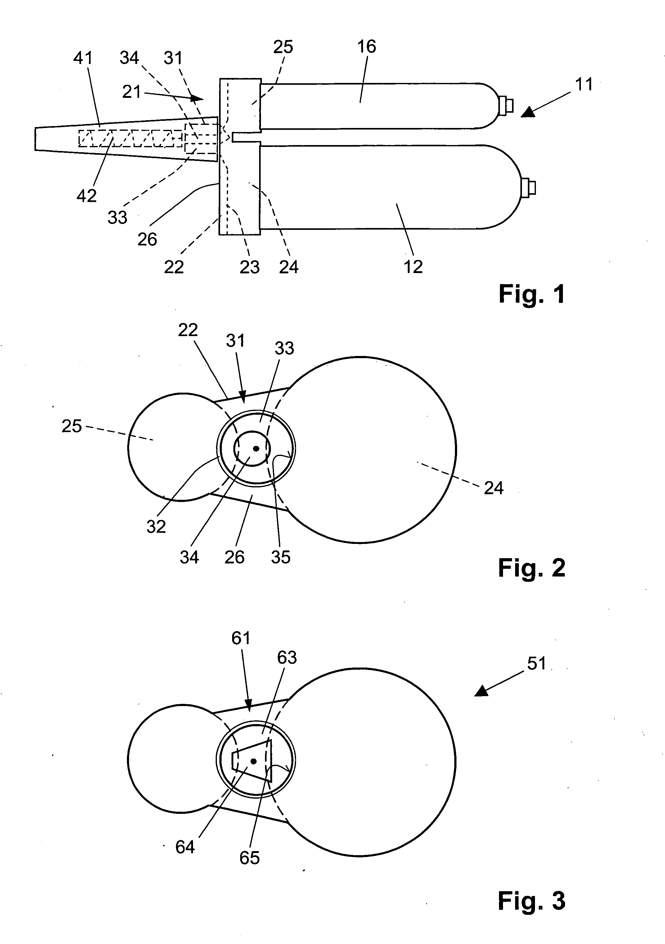
[0016]The clear cross-section of the at least one additional outlet opening is preferably round. For example, the clear cross-section of the at least one additional outlet opening is circular or oval. The head is easy to manufacture and ensures an advantageous combining of the compound components in the mixing element.
[0017]In another advantageous embodiment, the at least one second outlet opening has a polygonal clear cross-section. This head is likewise simple to manufacture and ensures an advantageous combining of the compound components in the mixing element. The at least one additional outlet opening advantageously has a trapezoidal clear cross-section.

Problems solved by technology

The known solution is disadvantageous in that, owing to the dividing wall in the mixer connection, the compound components flow parallel next to one another along the inner wall of the mixer connection when the foil container is squeezed.
Consequently, high ejection forces are required for dispensing the multi-component compound.

Method used


Image

  • Foil container with foil bag chambers which are arranged next to one another
  • Foil container with foil bag chambers which are arranged next to one another

Examples


Embodiment Construction

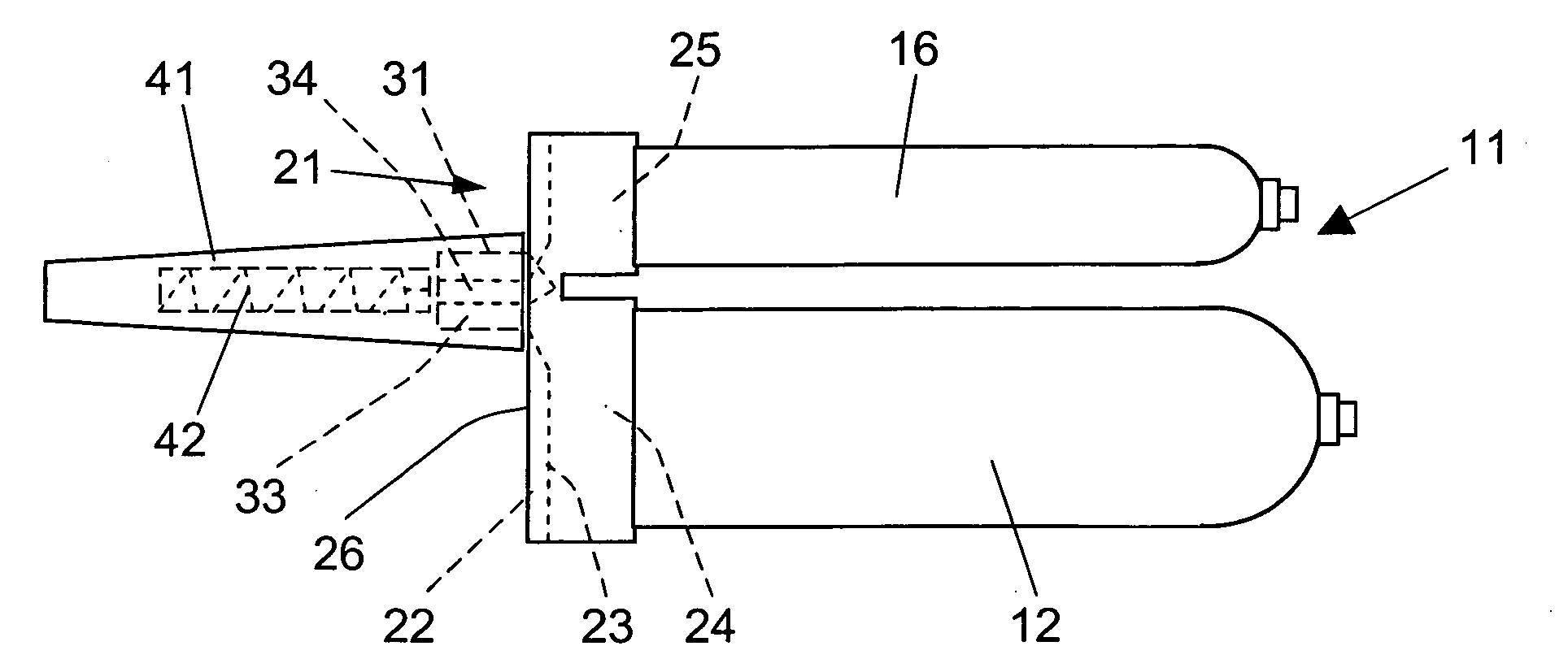
[0024]The foil container 11 according to the present invention and designed for storing a compound and for insertion into a receptacle of a ejection device, not shown, and which is shown in FIGS. 1 and 2, has two foil bag chambers 12 and 16 for compound components of a multi-component compound, which are stored separately from one another, and which foil bag chambers 12 and 16 are arranged next to one another. Further, the foil container 11 has a head 21 with a base plate 22 having, at a contact side 23, a receptacle portion 24 for one end of the foil bag chamber 12 and a receptacle portion 25 for one end of the foil bag chamber 16. A mixer connection 31 with an external thread 32 for the connection of a mixer housing 41 with a mixing element 42 is provided at a side 26 of the base plate 22 located opposite the contact side 23. In the mixer connection 31, there are provided a first outlet opening 33 with a circular clear cross-section defined by a wall 35 facing inward. The compound...


PUM


Abstract

A foil container (11) has two foil bag chambers (12, 16) arranged next to one another for compound components of a multi-component compound which are stored separately from one another, and a head (21) having a base plate (22) with a contact side (23) at which two receptacle portions (24, 25) are provided, each for one end of the respective foil bag chambers (12, 16), and a mixer connection (31) in which there are provided a first outlet opening (33) for one of the compound components of the multi-component compound and a second outlet opening (34) for an additional compound component of the multi-component compound and arranged in the first outlet opening (33).

Description

BACKGROUND OF THE INVENTION[0001]1. Field of the Invention[0002]The invention relates to a foil container for storing a compound and insertable in a receptacle of a ejection device and having foil bag chambers arranged next to one another for compound components of a multi-component compound which are stored separately from one another, and a head which has a base plate with a contact side at which at least one receptacle portion is provided for an end of the foil bag chambers, and a mixer connection at the base plate, with a first outlet opening for one of the compound components of the multi-component compound and at least one additional outlet opening for at least one additional compound component of the multi-component compound provided in the mixer connection.[0003]2. Description of the Prior Art[0004]Multi-component compounds such as, for example, mortar compounds, foam compounds, and sealing compounds are made available to the user as two-compound component or multi-component...

Claims


Application Information

Patent Timeline
Patent Type & Authority Applications(United States)
IPC IPC(8): B67D5/00B67D99/00
CPCB65D81/3244
Inventor PAETOW, MARIOKOEGLER, MARKUSHEFELE, CHRISTIANSCHELL, ANDREAS
Owner HILTI AG
Learn More