
Branching Device for a Pulsation Attenuation Network

Inactive Publication Date: 2009-04-02
ACI SERVICES
View PDF18 Cites 8 Cited by
  • Summary
  • Abstract
  • Description
  • Claims
  • Application Information

AI Technical Summary

Benefits of technology

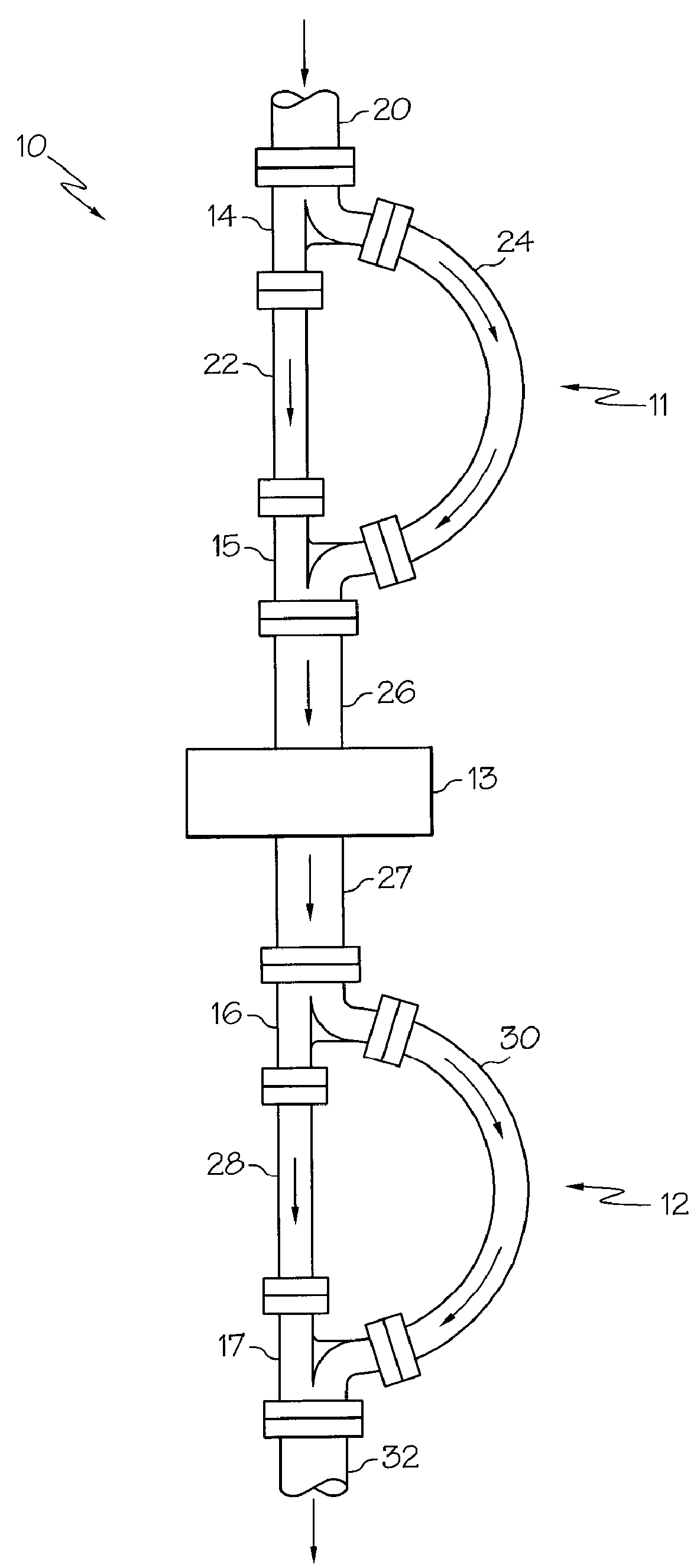
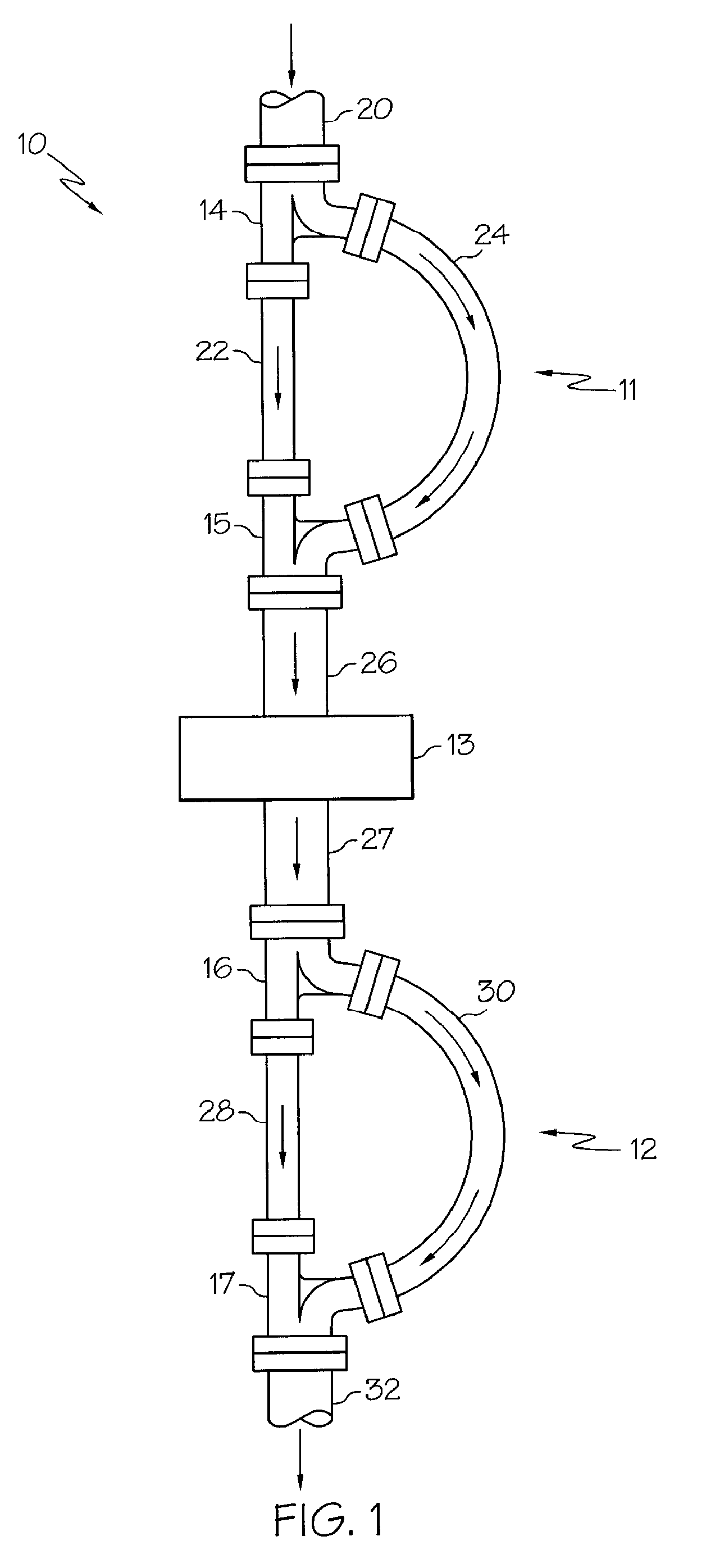
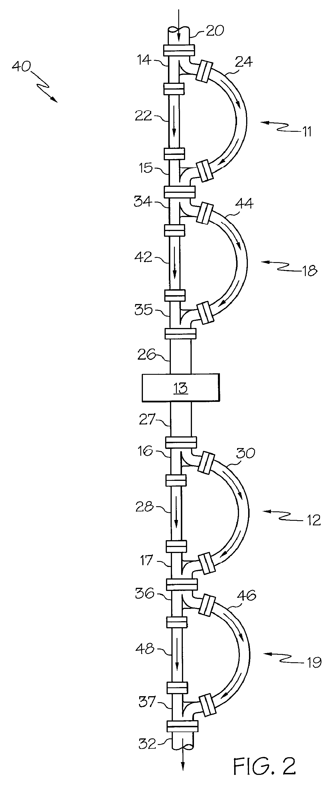
[0012]Accordingly, the present invention relates to a branching device for use with a pulsation attenuation network that significantly controls the pressure pulsation waves created by reciprocating compressor cylinders without causing significant pressure losses in the system. More specifically, the invention is a tuning section transition device intended for use with a pulsation attenuation network. The pulsation attenuation network typically includes one or more sequential stages of tuned delay loops that are split from the main pipe section and then subsequently rejoined to the main pipe section by the use of tuning section transition devices.
[0013]One aspect of the invention provides a branching device for creating a divergence point and / or a convergence point for a section of a pulsation attenuation network, the device comprising (a) a large flow channel; (b) two small flow channels; and (c) a divider that transitions the single large flow channel into the two small flow channels internally, wherein the divider is adapted to prevent the creation of significant disturbances in fluid flow patterns through the device.
[0014]Another aspect of the invention provides a branching device comprising (a) a first large flow channel; (b) a first divider adapted to transition the first large flow channel into a first small flow channel and a second small flow channel, wherein the second small flow channel is configured to diverge from the first small flow channel; (c) a third small flow channel adapted to converge with the first small flow channel into a second large flow channel; and (d) a second divider adapted to transition the first and third small flow channels into the second large flow channel, wherein the dividers are operable to prevent the creation of significant disturbances in fluid flow patterns through the device.
[0015]Another aspect of the invention provides a branching device for creating a divergence point and / or a convergence point for a section of a pulsation attenuation network, the device comprising (a) at least one large flow channel; (b) at least two small flow channels; and (c) at least one divider that transitions the large flow channel into the two small flow channels internally, wherein the divider is adapted to prevent the creation of significant disturbances in fluid flow patterns through the device, and wherein the device is adapted to accommodate flow in either direction.

Problems solved by technology

Over time, the magnitude of the pulsations may excite system mechanical natural frequencies, overstress system elements and piping, interfere with meter measurements, adversely affect cylinder performance, and affect the thermodynamic performance as well as the reliability and structural integrity of the reciprocating compressor and its piping system.
However, these devices typically accomplish pulsation attenuation by adding resistance to the system.
This added resistance causes system pressure losses both upstream and downstream of the compressor cylinders.
When using prior art pulsation attenuation devices, the resulting pressure drop typically increases as the frequency of the pulsation increases.
These pressure losses add to the work that must be done by the compressor to move fluid from the suction pipe to the discharge pipe.
Although improvements in system modeling have sometimes showed improved results using traditional pulsation attenuation devices, the problem of high system pressure losses continues to be a persistent issue, especially on high flow, low ratio reciprocating compressors.
The problem is more serious as energy costs and environmental regulations mandate improvements in system efficiency.
In some cases, system pressure drops have resulted in power losses exceeding 15 to 20%, and have been known to be as high as 30%.
As these larger high-speed reciprocating compressors have been increasingly used, pressure losses caused by the addition of traditional pulsation attenuation systems have become more problematic, due to the higher frequency pulsations that must be damped.
Significant pressure losses have also been encountered on high-speed compressors in some higher ratio applications, especially when a wide range of operating conditions is required.

Method used


Image

  • Branching Device for a Pulsation Attenuation Network
  • Branching Device for a Pulsation Attenuation Network
  • Branching Device for a Pulsation Attenuation Network

Examples


example case

[0058]Example Case: the application of this pulsation attenuation technology is discussed below. Finite amplitude wave compressor system simulation was used to model the current compressor system and also to design a tuned PAN system that effectively cancels the pressure pulsations with no significant pressure losses in the system.

[0059]The example case is a real two-cylinder field system configuration that has inlet scrubbers and primary and secondary pulsation bottles. Each side of a 6 in. stroke compressor has two 9.5 in. diameter double-acting cylinders that operate in parallel, but 180 degrees out of phase with each other. Two cylinders on each side of the compressor share common suction header bottles and common discharge header bottles. A finite amplitude wave simulation was conducted on this system after modeling the exact internal dimensions of the compressor cylinders, the inlet separator, suction and discharge pulsation bottles, and pipes that are currently in place. The ...


PUM


Abstract

A branching device or transition apparatus for controlling pulsation of a fluid in a piping system includes at least one large flow channel, at least two small flow channels, and at least one divider that transitions the single large flow channel into the two small flow channels internally, wherein the wall surfaces of the internal ports are generally smooth and continuous, and wherein the divider is adapted to prevent the creation of significant disturbances in fluid flow patterns through the device Typically the area of each of the small flow channels can be between about 25% to about 75% of the large flow channels, and the branching device can safely withstand pressures of between about 125 psig to about 2500 psig.

Description

CROSS REFERENCE TO RELATED APPLICATION[0001]This application claims the benefit of U.S. Provisional Application No. 60 / 976,075, filed Sep. 28, 2007.FIELD OF THE INVENTION[0002]The present invention relates in general to the control of the flow of pressurized fluids through industrial and commercial piping systems that include one or more reciprocating (piston-type) compressor cylinders, and in particular to a branching device for aiding in controlling pressure and flow pulsations of complex pressure waves passing through these systems without causing significant system pressure losses.BACKGROUND OF THE INVENTION[0003]Reciprocating compressors typically include one or more pistons that “reciprocate” within a closed cylinder. They are commonly used for a wide range of applications that include, but are not limited to, the pressurization and transport of air and / or natural gas mixtures through systems that are used for gas transmission, distribution, injection, storage, processing, ref...

Claims


Application Information

Patent Timeline
IPC IPC(8): F17D1/20F16L55/04
CPCF16L55/04F16L55/02763Y10T137/87265
Inventor SHADE, W. NORM
Owner ACI SERVICES
Learn More