
Projectile tracking system

a projectile tracking and projectile technology, applied in the field of infrared imaging methods and systems, can solve the problems of insufficient technology for detecting subsonic projectiles, inability to locate snipers, and inability to use existing counter-sniper targeting systems that use this technology in many cases, so as to achieve efficient and effective processing of the processing component.

Inactive Publication Date: 2009-03-26
LAU DANIEL L +1
View PDF26 Cites 21 Cited by
  • Summary
  • Abstract
  • Description
  • Claims
  • Application Information

AI Technical Summary

Benefits of technology

[0025]Advantageously, the steps of the invention are efficiently and effectively performed on the processing component. Therefore, another aspect of the invention is a computer readable medium having computer executable instructions for performing a method for determining the track of a projectile using a thermal signature of the projectile, as described above.

Problems solved by technology

However, this technology is not completely appropriate for detecting subsonic projectiles or for detecting supersonic projectiles that arrive at the target prior to the arrival of the acoustical energy generated by the firing of these projectiles.
Moreover, muzzle blasts are often interfered with by background noise (e.g. sea current, urban noises) and / or signals that have similar propagation speeds.
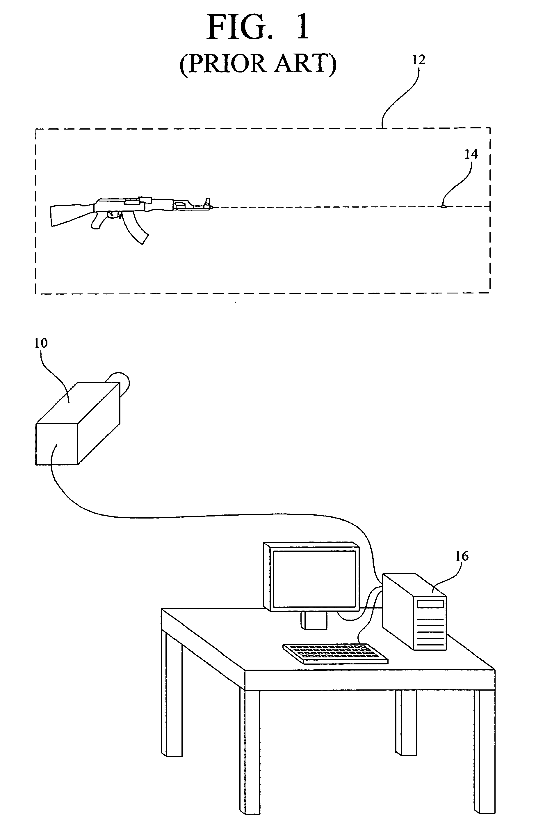
Even though IR imaging provides images that might represent the bullet discharge (muzzle flash) as well as the projectile in flight, the existing counter-sniper targeting systems that use this technology fail in many cases to locate a sniper.
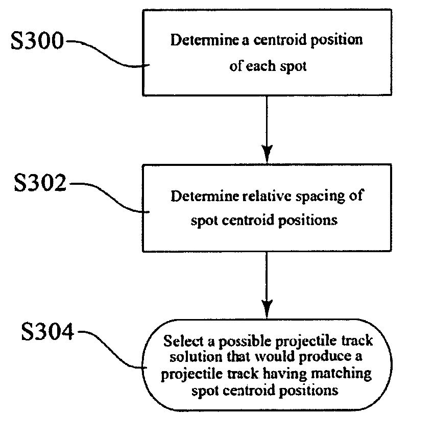
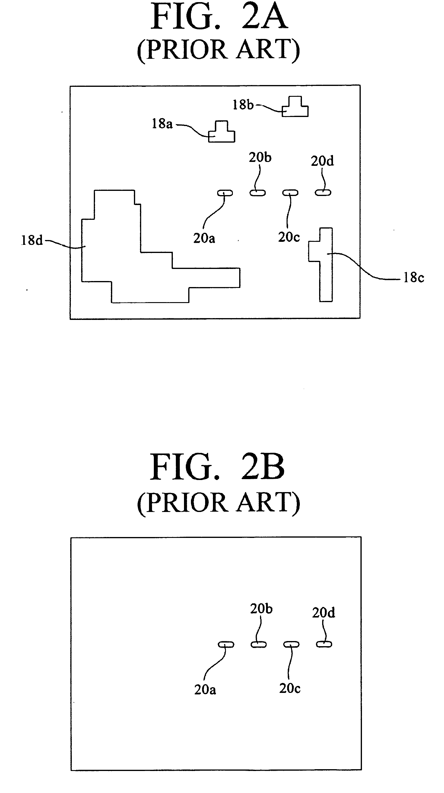
However, the series of spots 20a, 20b, 20c, 20d alone is not adequate to represent a unique bullet track solution since multiple bullet track solutions will produce successive images having substantially similar spots.
Thus, without additional information, such as time of fire (or the amount of time that the bullet was in flight prior to the infrared detector 10 detecting the first spot 20a), it is not possible to determine which bullet track solution is the correct or most accurate solution.
Because of the blended nature of the measured infrared radiation, simple frame differencing will not produce an accurate measure of the infrared radiation emitted by the bullet 14, and, therefore, cannot be used to accurately determine changes in the intensity of infrared radiation emitted from the bullet.
Thus, the issue of determining the path of a bullet by measuring changes in the intensity of infrared radiation emitted from the bullet is left unresolved.

Method used


Image

  • Projectile tracking system
  • Projectile tracking system
  • Projectile tracking system

Examples


Embodiment Construction

A. Every Projectile has a Unique “Thermal Signature”

[0048]FIG. 4 is a plan view of a plane defined by the location of an infrared sensor 40 and a projectile track, path, or trajectory 41. FIG. 4 shows how the composite thermal image of projectile spots over several image frames may appear with respect to the infrared sensor 40 at a given position (d1, d2) with respect to the location 42 from which the projectile is fired, where d is the shortest distance from the sensor 40 to the projectile path, and d2 is the distance along the projectile path from the firing location 42 to the closest point to the sensor 40.

[0049]FIG. 5 shows that, assuming that a projectile's path is a straight line, any projectile path, as well as the relative locations of the infrared sensor 40 and the location 42a, 42b, 42c from which the projectile is fired can be characterized by d1, d2, since in geometry, a line and a point define a plane.

[0050]Returning to FIG. 4, it is shown that the projectile spots chan...


PUM


Abstract

A system and method for determining the track of a projectile use a thermal signature of the projectile. Sequential infrared image frames are acquired from a sensor at a given position. A set of frames containing spots with characteristics consistent with a projectile in flight are identified. A possible projectile track solution for said spots is identified. A thermal signature value for each pixel of each spot of the possible solution is determined. The determined thermal signature is then compared to an actual thermal signature for a substantially similar projectile track to ascertain whether the determined thermal signature substantially matches the actual thermal signature, which indicates that the possible projectile track solution is the correct solution.

Description

CROSS-REFERENCE TO RELATED APPLICATIONS[0001]This application claims priority to U.S. Provisional Patent Application No. 60 / 684,541, filed May 25, 2005, which application is hereby incorporated by reference.STATEMENT REGARDING FEDERALLY SPONSORED RESEARCH OR DEVELOPMENT[0002]The U.S. Government has a paid-up license in this invention and the right in limited circumstances to require the patent owner to license others on reasonable terms as provided for by the terms of Contract No. M67854-02-D-110 awarded by the Marine Corps Systems Command.REFERENCE TO A “SEQUENTIAL LISTING,” A TABLE, OR A COMPUTER PROGRAM LISTING APPENDIX SUBMITTED ON A COMPACT DISC[0003]Not applicable.BACKGROUND OF THE INVENTION[0004]1. Field of the Invention[0005]The present invention relates to infrared imaging methods and systems. More particularly, this invention relates to determining the track of a projectile using a thermal signature fingerprint of the projectile.[0006]2. Description of Prior Art[0007]Exist...

Claims


Application Information

Patent Timeline
Patent Type & Authority Applications(United States)
IPC IPC(8): G06K9/00G01S17/86
CPCF41G3/147G01S17/66G01S17/023G01S17/86
Inventor LAU, DANIEL L.SHAW, MICHAEL F.
Owner LAU DANIEL L
Learn More