
Stirring state detecting method

Inactive Publication Date: 2009-03-26
PANASONIC CORP
View PDF7 Cites 1 Cited by
  • Summary
  • Abstract
  • Description
  • Claims
  • Application Information

AI Technical Summary

Benefits of technology

[0011]In accordance with the stirring state detecting method of the present invention, the stirring state of the test solution held in the container can be accurately detected without being affected by the ambient surroundings.

Problems solved by technology

However, in the case of using the method using the rotor which incorporates the magnetic body, the test solution may not be stirred adequately since the rotation of the rotor may not synchronize with the rotation of the magnet of the driving unit.

Method used


Image

  • Stirring state detecting method
  • Stirring state detecting method
  • Stirring state detecting method

Examples


embodiment 1

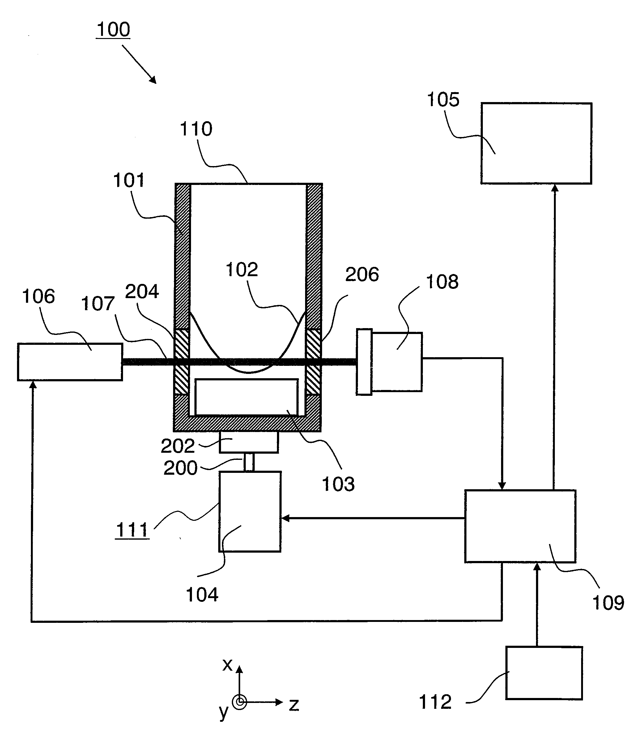
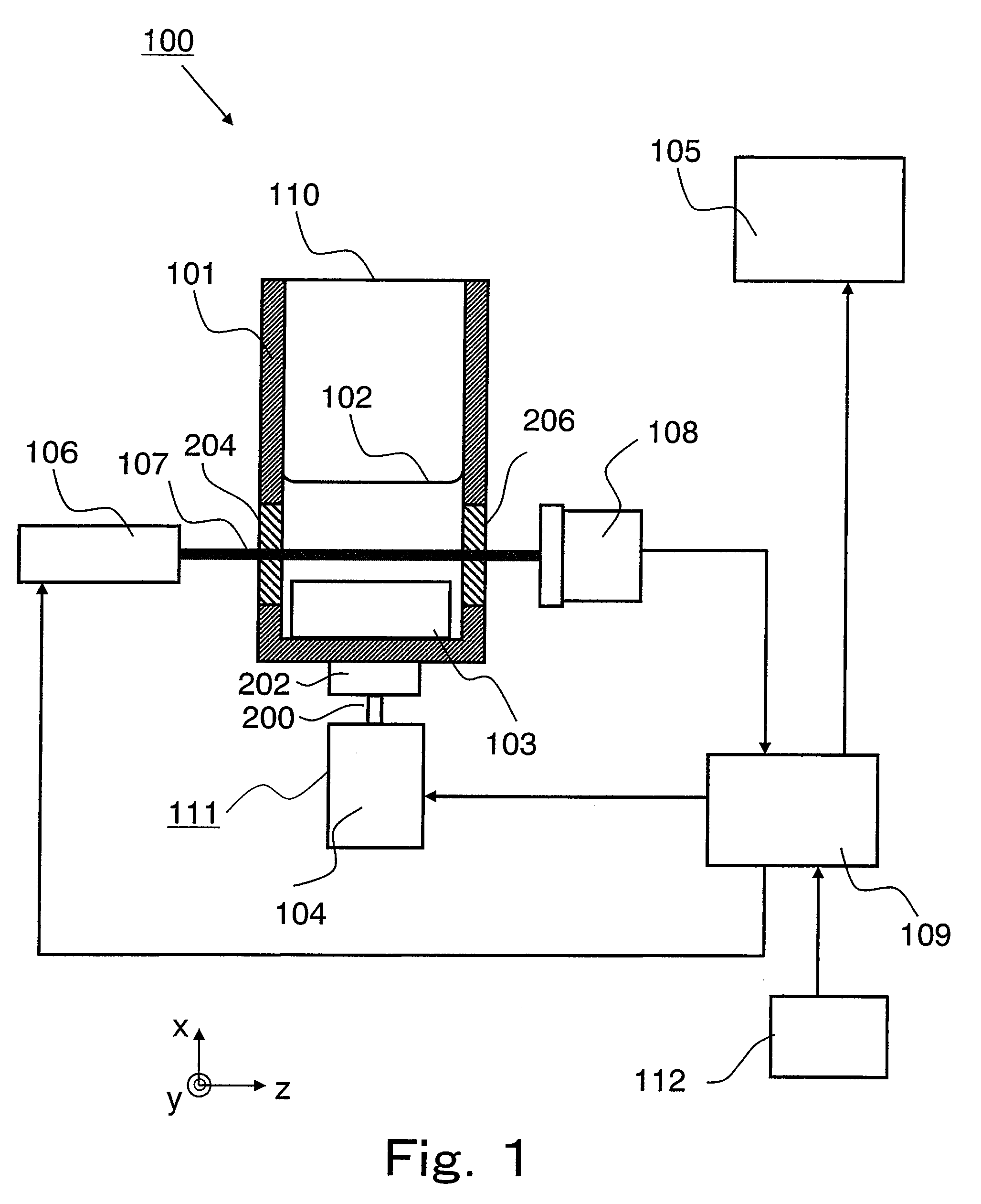
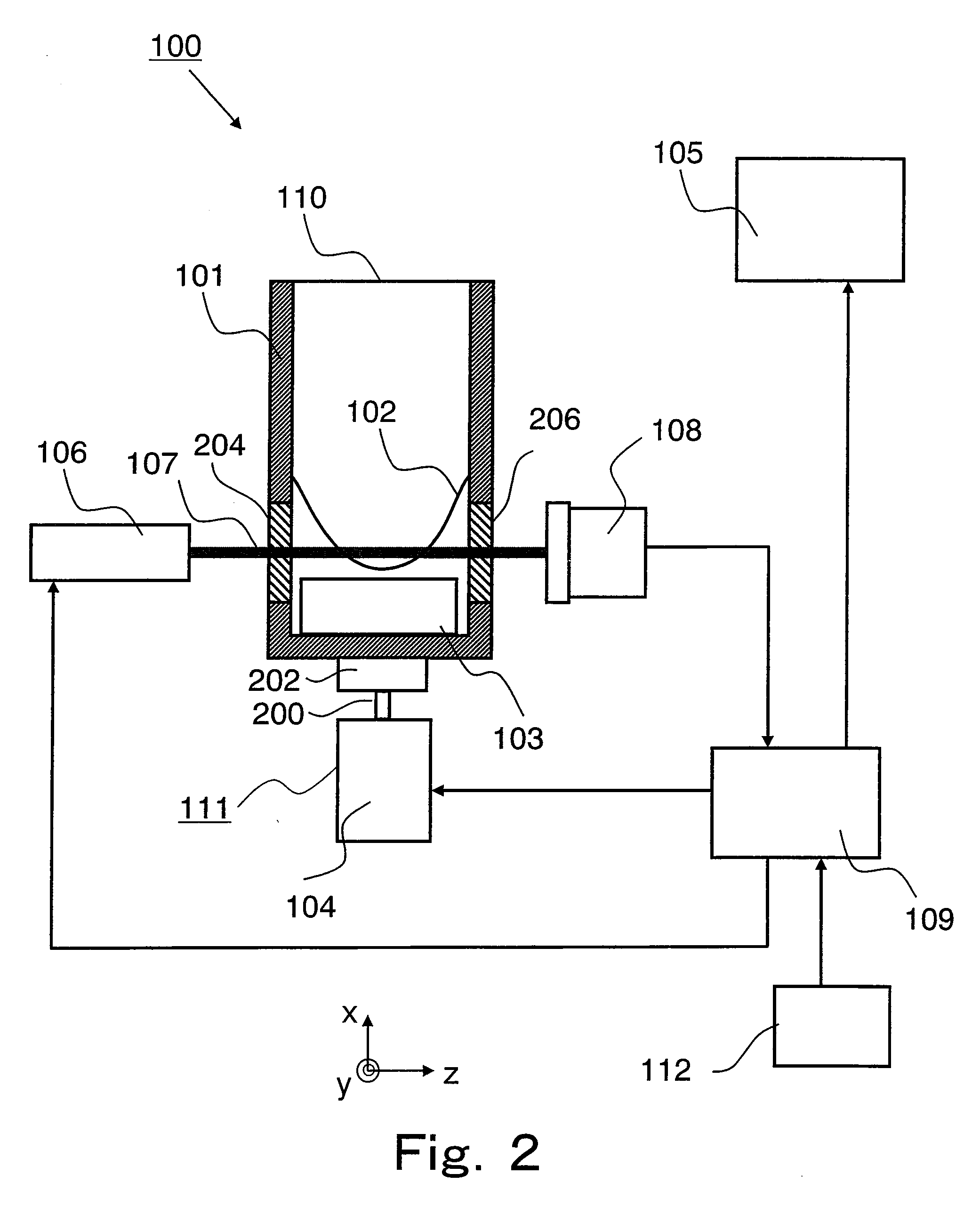
[0066]The stirring state detecting method according to Embodiment 1 of the present invention will be explained in reference to FIG. 1. FIG. 1 is a schematic diagram showing a schematic configuration of the optical measuring device used in the stirring state detecting method according to Embodiment 1 of the present invention.

[0067]As shown in FIG. 1, an optical measuring device 100 includes: a sample cell 101 which holds the test solution and in which a magnetic rotor 103 having a magnetic body is disposed; a magnetic rotor driving unit 104 which has a magnet 202 attached to a rotating shaft 200, and generates the change in the magnetic field which causes the magnetic rotor 103 to rotate; a semiconductor laser module 106 that is a light emitting device which emits light to the sample cell 101; an optical sensor 108 which receives transmitted light which has been transmitted through the sample cell 101 and emitted from the sample cell 101; a computer 109 constituted by a control unit ...

embodiment 2

[0124]Next, the stirring state detecting method according to Embodiment 2 of the present invention will be explained in reference to FIG. 7. FIG. 7 is a top view showing a schematic configuration of the optical measuring device used in the stirring state detecting method according to Embodiment 2.

[0125]As shown in FIG. 7, the optical measuring device 100 used in the stirring state detecting method according to Embodiment 2 of the present invention is different from the optical measuring device 100 of Embodiment 1 in that: the semiconductor laser module 106 and the optical sensor 108 are disposed such that the optical axis of the laser light 107 emitted from the semiconductor laser module 106 and a normal line with respect to a light receiving surface of the optical sensor 108 intersect with each other at a right angle; and accordingly, two optical windows 204 and 206 of the sample cell 101 are disposed on two adjacent side surfaces of four side surfaces surrounding the sample cell 1...

embodiment 3

[0146]Next, the stirring state detecting method according to Embodiment 3 of the present invention will be explained in reference to FIG. 11. FIG. 11 is a top view showing a schematic configuration of the optical measuring device used in the stirring state detecting method according to Embodiment 3.

[0147]The optical measuring device 100 shown in FIG. 11 is different from the optical measuring device 100 of Embodiment 1 in that a beam splitter 810 is included between the light source 106 and the sample cell 101. In addition, the optical measuring device 100 shown in FIG. 11 is different from the optical measuring device 100 of Embodiment 1 in that: the optical sensor 108 which receives backscattered light emitted from the sample cell 101 is included instead of the optical sensor 108 which receives the transmitted light; and only one optical window 204 is included. The other components are the same as those of Embodiment 1, so that explanations thereof are omitted.

[0148]In the optical...


PUM


Abstract

A stirring state detecting method of the present invention is a method for detecting a stirring state of a test solution by using: a sample cell (101) which holds the test solution in an internal space thereof; a stirring device (111) which stirs the test solution held in the sample cell (101); a light emitting device (106) which emits light to the test solution held in the sample cell (101); and a photoreceiver (108) which receives the light, and includes the steps of: (A) in a state in which the test solution is held in the sample cell (100), activating the stirring device (111) to change a liquid level (102) of the test solution by stirring; (B) emitting the light from the light emitting device (106) to the test solution held in the sample cell (100); (C) detecting by the photoreceiver (108) an amount of the light which is emitted to the test solution and subjected to an action of the test solution whose liquid level (102) is changed by the stirring; and (D) determining the stirring state of the test solution based on the amount of the light detected by the photoreceiver (108) in the step (C).

Description

TECHNICAL FIELD[0001]The present invention relates to a stirring state detecting method used when mixing, by stirring, a sample solution and a reagent held in a container.BACKGROUND ART[0002]Generally, it is desirable that when measuring an optical property of a test solution containing a sample solution and a reagent, the sample solution and the reagent be uniformly mixed in the test solution. Therefore, the test solution containing the sample solution and the reagent held in the container is stirred before measuring the optical property.[0003]Proposed as a method for stirring the test solution held in the container is, for example, a method using a rotor which incorporates a magnetic body. For example, in accordance with a method disclosed in Patent Document 1, the container including the rotor is mounted on a driving unit including an electric motor in which a magnet is attached to a rotating shaft, and the rotor is rotated by rotation of the electric motor of the driving unit, t...

Claims


Application Information

Patent Timeline
IPC IPC(8): G01N21/59B01F35/60
CPCB01F13/0818B01F15/00123G01N2035/00534G01N2021/5988G01N21/59B01F33/452B01F35/20
Inventor MURAOKA, JINKAWAMURA, TATSUROU
Owner PANASONIC CORP
Learn More