Digital Camera with Interchangeable Lens and an Electronic Viewfinder

a digital camera and lens technology, applied in the field of digital cameras, can solve the problems of blurred images, increased vibration, and considerable mechanical challenges, and achieve the effect of eliminating discomfort for viewers and tracking targets more effectively

Inactive Publication Date: 2009-03-26
LIAO YORK
View PDF5 Cites 15 Cited by
  • Summary
  • Abstract
  • Description
  • Claims
  • Application Information

AI Technical Summary

Benefits of technology

[0005]Accordingly, the present invention provides a digital camera with a lens module which focuses incident light from an external image to a focal plane. A microprocessor is provided for controlling the function of the camera. An image sensor array located at the focal plane is coupled to the microprocessor and includes a plurality of pixel elements. The image sensor array is capable of converting the incident light energy shone on the plurality of pixel elements to electrical signal. A high resolution display panel is coupled to the microprocessor and capable of receiving the electrical signal from the image sensor array and projecting an electronic image for a viewer to preview. An eyepiece is provided and is adapted to receive and magnify the projected electronic image to a viewer. The camera is designed such that it does not need any mechanism to produce a through-the-lens true optical image for the viewer to preview, yet is able to provide a high resolution through-the-lens electronic image that has a resolution equivalent to at least 200 dots per inch (dpi) when seen by the viewer through the eyepiece, such that the viewer can preview the external image that he wishes to capture at a quality that is equivalent to an optical image in the absence of any corresponding optical reflective element in the camera.
[0011]The present invention, which replaces the existing OVF systems with an electronic viewfinder (EVF), has many advantages over its optical counterpart. Firstly, the absence of reflective flip mirror 28 in the present invention means that there are no moving parts inside camera shell 48. This means no vibration is generated when a viewer is capturing an image. The vibration is associated with the flipping motion of reflective flip mirror 28 to let incoming light reach image sensor array 42. Since reflective flip mirror 28 is provided very close to image sensor array 42, the vibration is very likely to affect image sensor array 42. By eliminating the moving part and vibration, the EVF system is able to give a sharper captured image.
[0012]In addition, whereas reflective flip mirror 28 of existing TTL OVF system blocks the viewer's view each time an image is taken, the EVF system is able to give the viewer an uninterrupted preview of image. This is a big improvement when taking sequential shots. A continuous preview enables the viewer to track a target more effectively, especially for fast moving targets. It also eliminates the discomfort caused to the viewer from consecutive switches from seeing a preview image to seeing total darkness, which will be the case if each shot is taken by time exposure.

Problems solved by technology

Such movement invariably introduces vibration to image sensor array 42, causing the image being captured to become blurred.
This is done at considerable mechanical challenge and the vibration it induces is more significant.
Lastly, the entire viewfinder assembly is relatively bulky.
However, as a substantial portion of the light intensity is diverted to the viewfinder, only a fraction of the incident light reaches the image sensor array 42 for picture taking, thus degrading the picture quality, especially when used in low light situations.

Method used


Image

  • Digital Camera with Interchangeable Lens and an Electronic Viewfinder
  • Digital Camera with Interchangeable Lens and an Electronic Viewfinder
  • Digital Camera with Interchangeable Lens and an Electronic Viewfinder

Examples


Embodiment Construction

[0020]As used herein and in the claims, “comprising” means including the following elements but not excluding others. When interpreting each statement in this specification that includes the term “comprising”, features other than that or those prefaced by the term may also be present. Related terms such as “comprise” and “comprises” are to be interpreted in the same manner.

[0021]As used herein and in the claims, “couple” or “connect” refers to electrical coupling or connection either directly or indirectly via one or more electrical means unless otherwise stated.

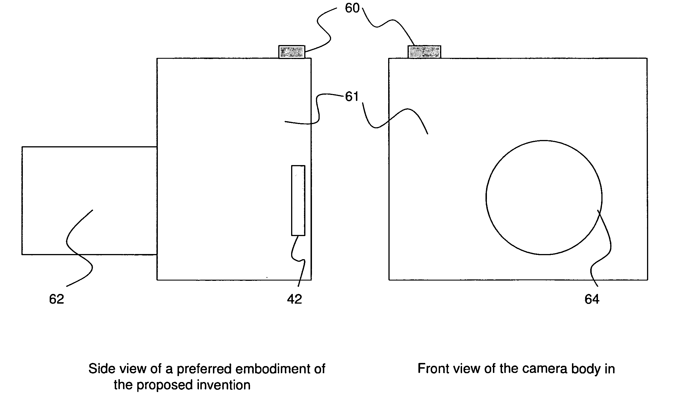
[0022]Referring now to the conceptual diagrams of the present invention as shown in FIGS. 3a and 3b, a preferred embodiment includes a camera body 61 and a lens module 62. Camera body 61 includes a camera shell 48 with a shutter button 60. There is a circular opening 64 at the front of the camera body 61 where lens module 62 can be mounted. An image sensor array 42 is mounted within the camera shell 48 towards the back and i...


PUM


Abstract

This invention provides an alternative to a digital single lens reflex camera, by not providing a through-the-lens optical image for the viewer to preview, while providing a high resolution through-the-lens electronic image that has a resolution equivalent to at least 200 dpi when seen by the viewer through the eyepiece, such that the viewer can preview the external image that he wishes to capture at a quality that is equivalent to an optical image, in the absence of any corresponding optical reflective element in the camera. The advantage of the present invention is that the quality of preview image is maintained while solving some of the problems in an OVF.

Description

FIELD OF INVENTION[0001]This invention relates to a digital camera, in particular a digital camera with interchangeable lens and an electronic viewfinder.BACKGROUND OF INVENTION[0002]In existing digital single lens reflex (DSLR) camera, a through-the-lens (TTL) optical viewfinder (OVF) is used for previewing, framing and focusing. In such a viewfinder, an optical preview image is reflected to a viewer using the focusing lens of the camera through a reflective flip mirror. The major components of a conceptual optical viewfinder in a DSLR camera are shown in FIG. 1a. A reflective flip mirror 28 is positioned inside the camera shell 48 along the optical axis 21 of the camera to reflect incident light from the focusing lens assembly 22 upward along the reflected optical axis 29. A focusing screen 30 is provided that is aligned to reflect optical axis 29 and is capable of showing a sharp frame if the image is focused. A condensing lens 32 is provided along reflected optical axis 29 to gu...

Claims


Application Information

Patent Timeline
Patent Type & Authority Applications(United States)
IPC IPC(8): G02B27/10
CPCG03B13/24H04N5/23293G03B19/02G03B17/20H04N23/651H04N23/63
Inventor LIAO, YORK
Owner LIAO YORK
Why Eureka
Try Eureka