
Power supply having an auxiliary power cell

a power cell and power supply technology, applied in the field of power supplies, can solve the problems of power cell power supply capability, power system performance degradation, power cell power supply ability, etc., and achieve the effect of reducing power supply capability

Inactive Publication Date: 2009-03-26
COCHLEAR LIMITED
View PDF43 Cites 14 Cited by
  • Summary
  • Abstract
  • Description
  • Claims
  • Application Information

AI Technical Summary

Benefits of technology

The present invention provides a power supply that can efficiently supply power to a load. The power supply includes multiple power cells connected in series, and an auxiliary power cell that can be added in parallel with one of the power cells to increase the overall power delivery capability. The control module can selectively connect the auxiliary cell with the power cell that has lower power delivery capability. This allows for a more flexible and effective power supply that can adapt to different load requirements.

Problems solved by technology

For example, if a power supply provides insufficient power, a powered system may fail unexpectedly or erratically.
The ability of a power cell to output power, sometimes referred to as the power cells' power delivery capability, may be limited by the power cell's size, shape, type, condition, etc.
A particular problem associated with conventional power supplies is that failure of a single power cell may limit the power available to the powered system, thereby causing performance of the system to degrade, or causing unexpected system shutdown.
For example, a decrease in the operating voltage of a single power cell could result in total system shutdown or failure.
In certain powered systems, loss or interruption of power results in, for example, total system failure, loss of information, or damage to the various components of the powered system.
As such, unexpected or erratic failures, or failure to meet additional power demands, is undesirable, and, at times, unacceptable.
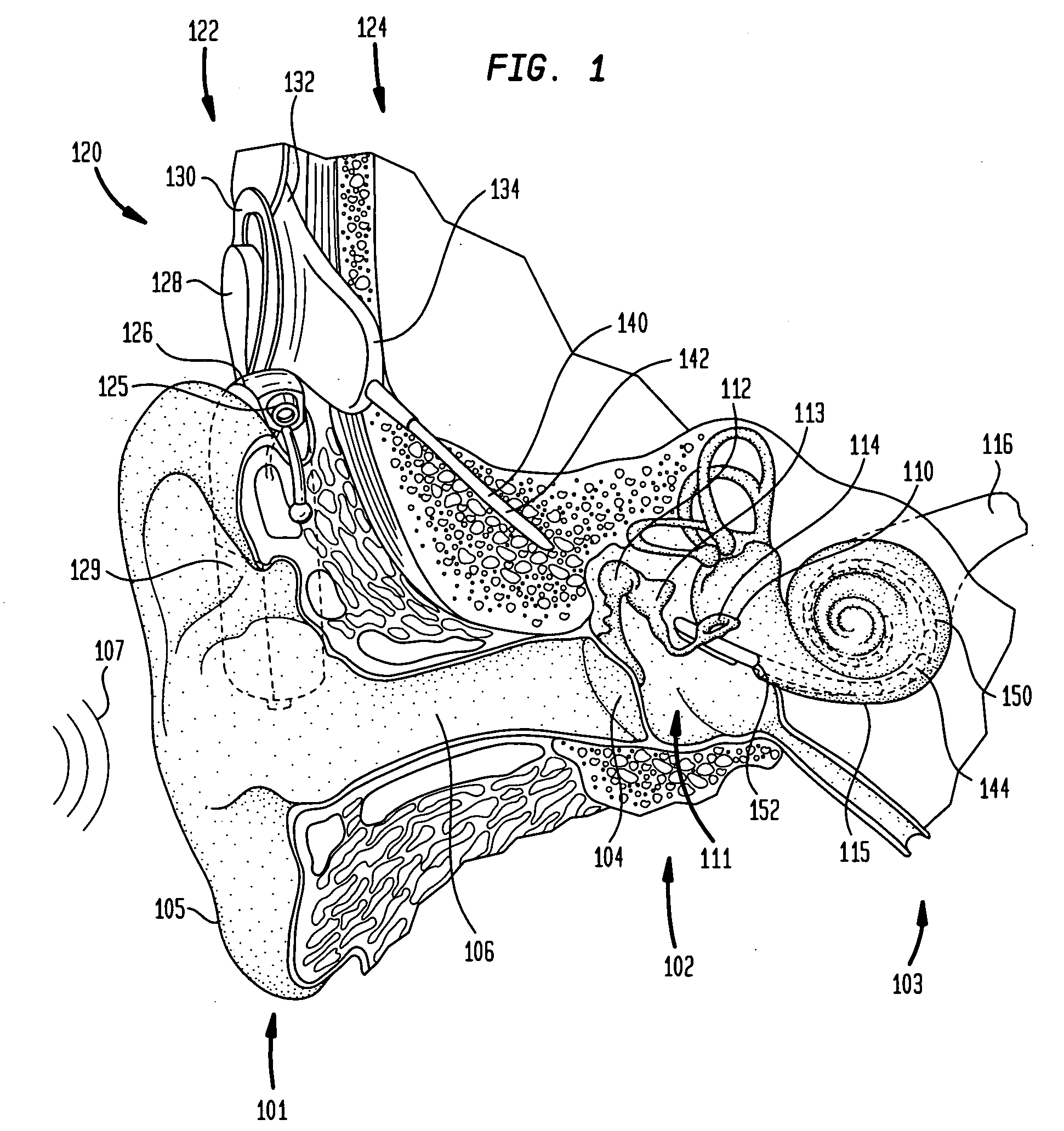
Examples of powered systems in which such failures are often unacceptable include medical prostheses such as neural stimulators, pacers, drug pumps, hearing prostheses, and the like.
The power system may continue to operate in one of these states using the available power to operate only critical components, or the system may eventually shut down.
Although damage to the powered system may be avoided, the ability to extend meaningful operation of the system beyond interruption of power is not possible.

Method used


Image

  • Power supply having an auxiliary power cell
  • Power supply having an auxiliary power cell
  • Power supply having an auxiliary power cell

Examples


Embodiment Construction

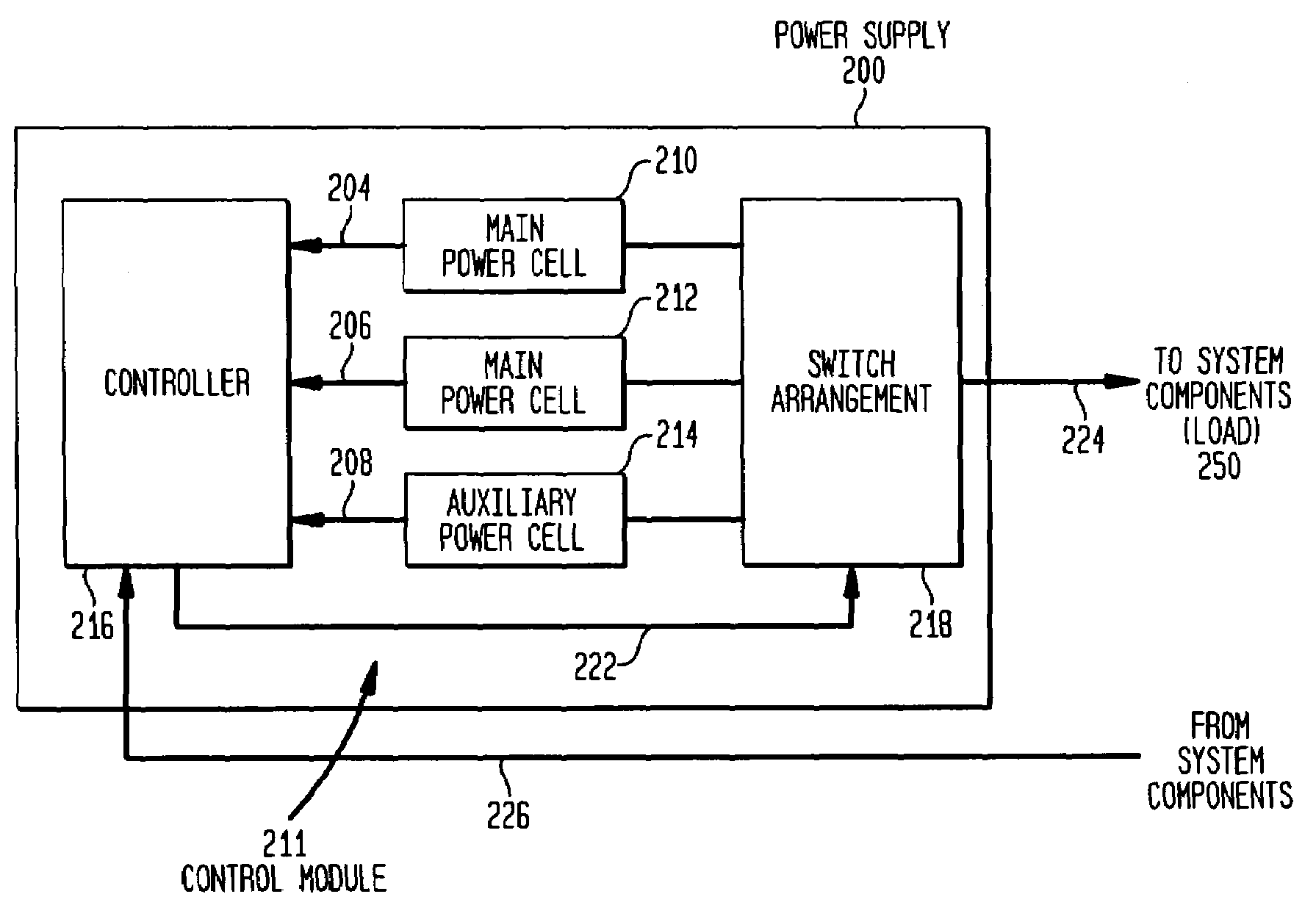
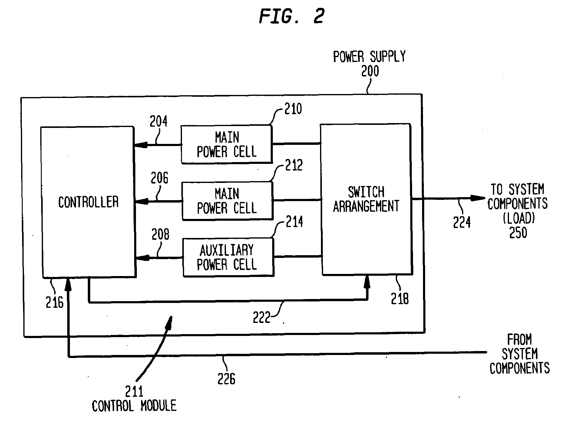
[0022]Aspects of the present invention are generally directed to a power supply having selectively electrically connectable power cells to supply power to a load. The power supply comprises a plurality of power cells electrically connected in series with one another, (sometimes referred to herein as “serially connected power cells” or as a “series configuration of power cells”), and an auxiliary power cell connected in parallel with one of the serially connected power cells. A control module selectively connects the auxiliary cell in parallel with whichever one of the serially connected power cells has a lower power delivery capability. In accordance with embodiments of the present invention, the power delivery capability of the serially connected power cells may be re-evaluated to determine which power cell currently has the lower power delivery capability.

[0023]In one embodiment, the power delivery capability of a power cell is determined by measuring the operating voltage of a po...


PUM


Abstract

A power supply having a plurality of selectively electrically connectable power cells configured to supply power to a load. The power supply comprises a plurality of power cells electrically connected in series and an auxiliary power cell electrically connected in parallel with one of said plurality of power cells. A control is configured to selectively electrically connect said auxiliary cell in parallel with whichever one of said plurality of power cells has a lower power delivery capability.

Description

CROSS-REFERENCE TO RELATED APPLICATIONS[0001]This application is a continuation-in-part of U.S. patent application Ser. No. 11 / 645,729 filed on Dec. 27, 2006, now pending, which is a Continuation of U.S. patent application Ser. No. 10 / 250,705 filed on Jul. 7, 2003, now issued as U.S. Pat. No. 7,157,808, which is a National Stage application of International Application PCT / AU2002 / 000074 filed on Jan. 24, 2002, which claims priority from Australian Patent Application PR 2693, which was filed on Jan. 24, 2001, all of which are hereby incorporated by reference herein.BACKGROUND[0002]1. Field of the Invention[0003]The present invention relates generally to power supplies, and more particularly, to a power supply having an auxiliary power cell.[0004]2. Related Art[0005]Electrochemical power cells, solar power cells, fuel power cells, etc, (generally and collectively referred to as “power cells” herein) are used to generate and / or store electrical energy. One or more power cells are conve...

Claims


Application Information

Patent Timeline
Patent Type & Authority Applications(United States)
IPC IPC(8): H02J7/34
CPCA61N1/36032A61N1/378H04R25/606H02J7/0063H02J7/0024A61N1/36038H02J7/007182H02J2310/23
Inventor SELIGMAN, PETER
Owner COCHLEAR LIMITED
Learn More