
Floating Absorber Assembly for Reduced Fuel Slosh Noise

a technology of absorber and fuel slosh, which is applied in the field of fluid tanks, can solve the problems of difficult incorporation of baffles or absorbers within plastic fuel tanks, particularly blow-molded plastic tanks, and the noise of slosh to become particularly loud, and achieve the effect of reducing fuel slosh noise and mitigating surface wave propagation

Inactive Publication Date: 2009-03-26
HONDA MOTOR CO LTD
View PDF35 Cites 62 Cited by
  • Summary
  • Abstract
  • Description
  • Claims
  • Application Information

AI Technical Summary

Benefits of technology

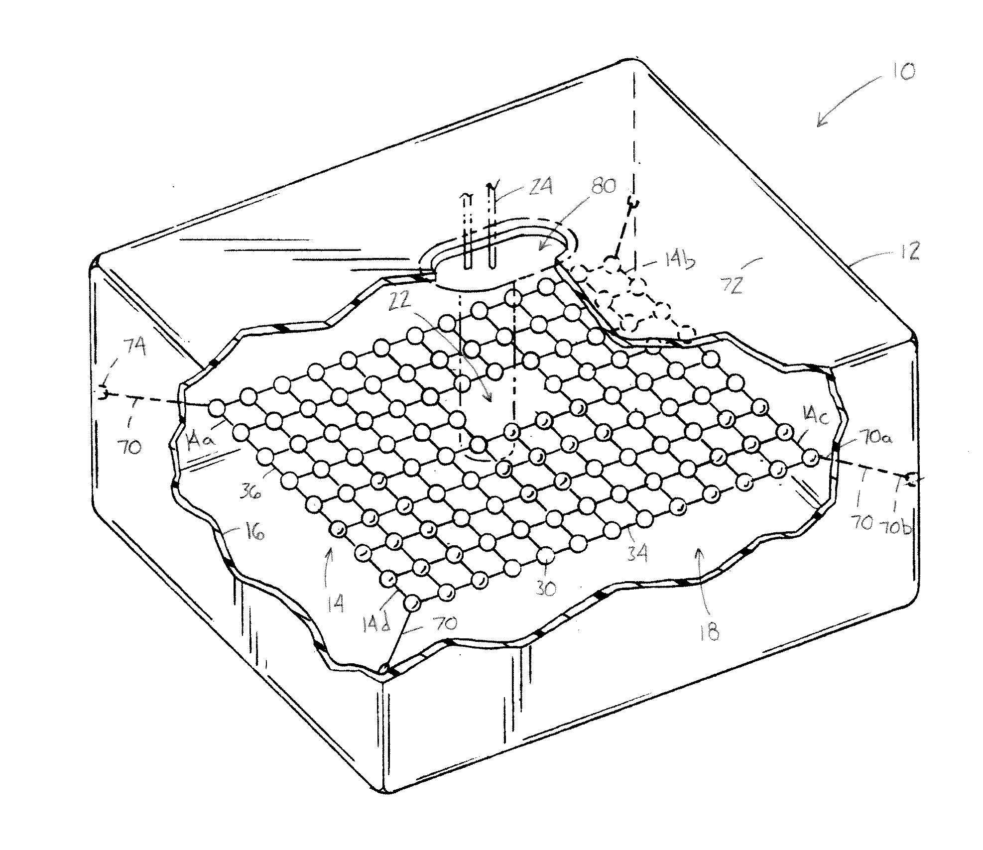
[0008]In accordance with another aspect, an absorber assembly for a fuel tank of a motor vehicle for reducing fuel slosh noise comprises a plurality of dampener elements for mitigating surface wave propagation. The plurality of dampener elements are linked together to form a matrix of dampener elements. The absorber assembly is suspended within a cavity defined by an inner surface of the tank such that the absorber assembly is spaced from the tank inner surface. The dampener elements have a specific density smaller than that of the fuel in the tank so as to float on a surface of the fuel at critical fuel volumes.
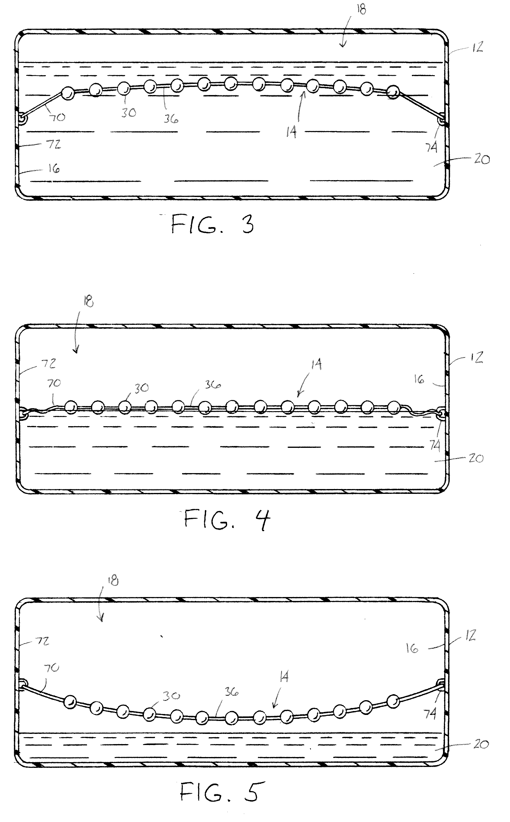
[0009]In accordance with yet another aspect, an absorber assembly for a fuel tank of a motor vehicle for reducing fuel slosh noise comprises a plurality of generally spherical, interconnected dampener elements. The dampener elements have a mat-like configuration tethered within a cavity defined by an inner surface of the fuel tank to mitigate surface wave propagation. A plurality of tethers attach the interconnected dampener elements to side portions of the tank inner surface. The tethers prevent the dampener elements from contacting the side portions and allow the dampener elements to float on the fuel surface when a volume of fuel within the tank is between a first critical fuel volume and a second, lower critical fuel volume. The absorber assembly is generally submerged when a volume of liquid within the tank is a generally greater than the first critical volume. The absorber assembly is generally suspended within the cavity when a volume of liquid within the tank is a generally lower than the second critical volume.

Problems solved by technology

The incorporation of baffles or absorbers within plastic fuel tanks, particularly blow-molded plastic tanks, is difficult due to manufacturability problems and reduced fuel volume concerns.
This can cause the sloshing noise to become particularly loud.
This approach is cumbersome, work-intensive and expensive, especially inside a plastic fuel tank where the only access to the interior of the tank is typically through a single opening for the fuel pump.
However, they can require a relatively large amount of space to be effective, which unnecessarily restricts the filling capacity of the fuel tank.

Method used


Image

  • Floating Absorber Assembly for Reduced Fuel Slosh Noise
  • Floating Absorber Assembly for Reduced Fuel Slosh Noise
  • Floating Absorber Assembly for Reduced Fuel Slosh Noise

Examples


Embodiment Construction

[0017]It should, of course, be understood that the description and drawings herein are merely illustrative and that various modifications and changes can be made in the structures disclosed without departing from the present disclosure. It will also be appreciated that the various identified components of the absorber assembly disclosed herein are merely terms of art that may vary from one manufacturer to another and should not be deemed to limit the present disclosure. All references to direction and position, unless otherwise indicated, refer to the orientation of the absorber assembly illustrated in the drawings and should not be construed as limiting the claims appended hereto.

[0018]Referring now to the drawings, wherein like numerals refer to like parts throughout the several views, FIG. 1 illustrates a liquid tank assembly 10 for an associated motor vehicle (not shown). The liquid tank assembly generally comprises a tank 12 and an absorber assembly 14 having a mat-like, net-li...


PUM


Abstract

A liquid tank assembly for a motor vehicle includes a tank and an absorber assembly. The tank has an inner surface defining a cavity for receiving a liquid substance. The absorber assembly is disposed within the cavity for dampening liquid sloshing noises. The absorber assembly includes a plurality of connected dampener elements. End sections of the absorber assembly are attached to the inner surface of the tank. The absorber assembly is configured to float on a surface of the liquid when a volume of liquid within the tank is between a first critical volume and a second, lower critical volume. The absorber assembly is generally submerged when a volume of liquid within the tank is a generally greater than the first critical volume. The absorber assembly is generally suspended within the cavity when a volume of liquid within the tank is a generally lower than the second critical volume.

Description

BACKGROUND[0001]The present disclosure generally relates to a fluid tank, such as a fuel tank, for a motor vehicle. More particularly, the present disclosure relates to a floating absorber assembly disposed in a fuel tank for reducing fuel slosh noise.[0002]Sloshing noises that originate inside a fluid tank of a motor vehicle, such as a fuel tank, are generally due to the movement of liquid (e.g., fuel) that occurs during driving. In a vehicle's fuel tank, this sloshing noise can sometimes be heard inside the vehicle's passenger cabin, particularly at certain critical fuel volumes, and is considered a nuisance.[0003]Historically, vehicle fuel tanks were made of steel. Noise or fuel slosh reducing baffles, including vertically-oriented absorbers, are more easily incorporated into steel fuel tanks for purposes of inhibiting the formation of waves within the fuel tank thereby reducing or eliminating noise or fuel slosh within the tank. More recently, many vehicle fuel tanks have been m...

Claims


Application Information

Patent Timeline
Patent Type & Authority Applications(United States)
IPC IPC(8): B65D90/02
CPCB60K15/077B60K2015/0775B60K2015/0344
Inventor RAMSAY, THOMAS N.
Owner HONDA MOTOR CO LTD
Learn More