
Body fluid treating filter device

a filter device and body fluid technology, applied in filtration separation, separation processes, chemistry apparatuses and processes, etc., can solve the problems of insufficient blood recovery, insufficient pressure recovery of body fluid, and increased pressure in the device, and achieve excellent body fluid recovery performan

Active Publication Date: 2009-03-26
ASAHI KASEI MEDICAL CO LTD
View PDF9 Cites 57 Cited by
  • Summary
  • Abstract
  • Description
  • Claims
  • Application Information

AI Technical Summary

Benefits of technology

[0014]The body fluid-treating filter device of the present invention can maintain the treating pressure of the filter device in a clinically safe range during operation for a long period of time and can exhibit excellent body fluid recovery performance, leaving only a small amount of reside in the device after completion of a body fluid treatment.

Problems solved by technology

When such a body fluid-treating filter device is actually used, the pressure in the device increases in some cases depending on the state of the blood to be treated, for example, when the amount of a blood anticoagulant added is insufficient or the blood anticoagulant is mixed only insufficiently.
In other cases, when a physiological solution is caused to flow in order to recover the blood from the filter device, the physiological solution does not necessarily flow through the entire filter device, resulting in insufficient recovery of the body fluid.
Although this filter device has an effect of efficiently filling a body fluid-treating filter in a housing, countermeasures against the pressure increase and blood poor recovery were still insufficient since the essential structure remained the same as above.
As mentioned above, commonly used fluid-treating filter devices have problems besides basic performance that should be still improved as a medical apparatus.

Method used


Image

  • Body fluid treating filter device
  • Body fluid treating filter device
  • Body fluid treating filter device

Examples


example 1

Preparation of Cylindrical Filter Material

[0065]The cylindrical filter layer used in Examples and Comparative Examples was prepared by winding a spacer material used as an inner side spacer layer around a rod-shaped member for assembly to be used as a core in the shape of a roll of cloth, winding a spacer material to be used as an outer side spacer layer while controlling torque to make the external diameter of the outer side spacer 38 mm, and extracting the rod-shaped member.

[0066]First, polyethylene mesh (mesh size: 8, thickness: 0.75 mm, width: the same as the housing length), which is the spacer material to be used as the inner side spacer layer, was wound two rounds around the rod-shaped member to make the inner diameter 15 mm or more and the outer diameter 18 mm. Next, as a filter layer, the filter material was directly wound around the rod-shaped member for assembly use (the inner side spacer layer was not provided in Comparative Example 4). After that, the same assembly proc...

example 2

[0069]A body fluid-treating filter device according to the specification of Example 1 was obtained in the same manner as in Example 1, except that a flow passage resistant member with a diameter of 11 mm was used and polyethylene mesh, which is the spacer material to be used as the inner side spacer layer, was wound four rounds to make the inner diameter 11 mm or more and the outer diameter 18 mm.

example 3

[0070]A body fluid-treating filter device according to the specification of Example 1 was obtained in the same manner as in Example 1, except that a flow passage resistant member with a diameter of 18 mm was used and polyethylene mesh (mesh size: 9, thickness: 0.525 mm), which is the spacer material to be used as the inner side spacer layer, was wound one round to make the inner diameter 18 mm or more and the outer diameter 19.4 mm. In this example, in order to make the outer diameter of the outer side spacer layer 38 mm, torque was more tightly controlled than in the filter layer and the outer side spacer layer of the other examples and comparative examples.


PUM

PropertyMeasurementUnit
thicknessaaaaaaaaaa
thicknessaaaaaaaaaa
thicknessaaaaaaaaaa

Abstract

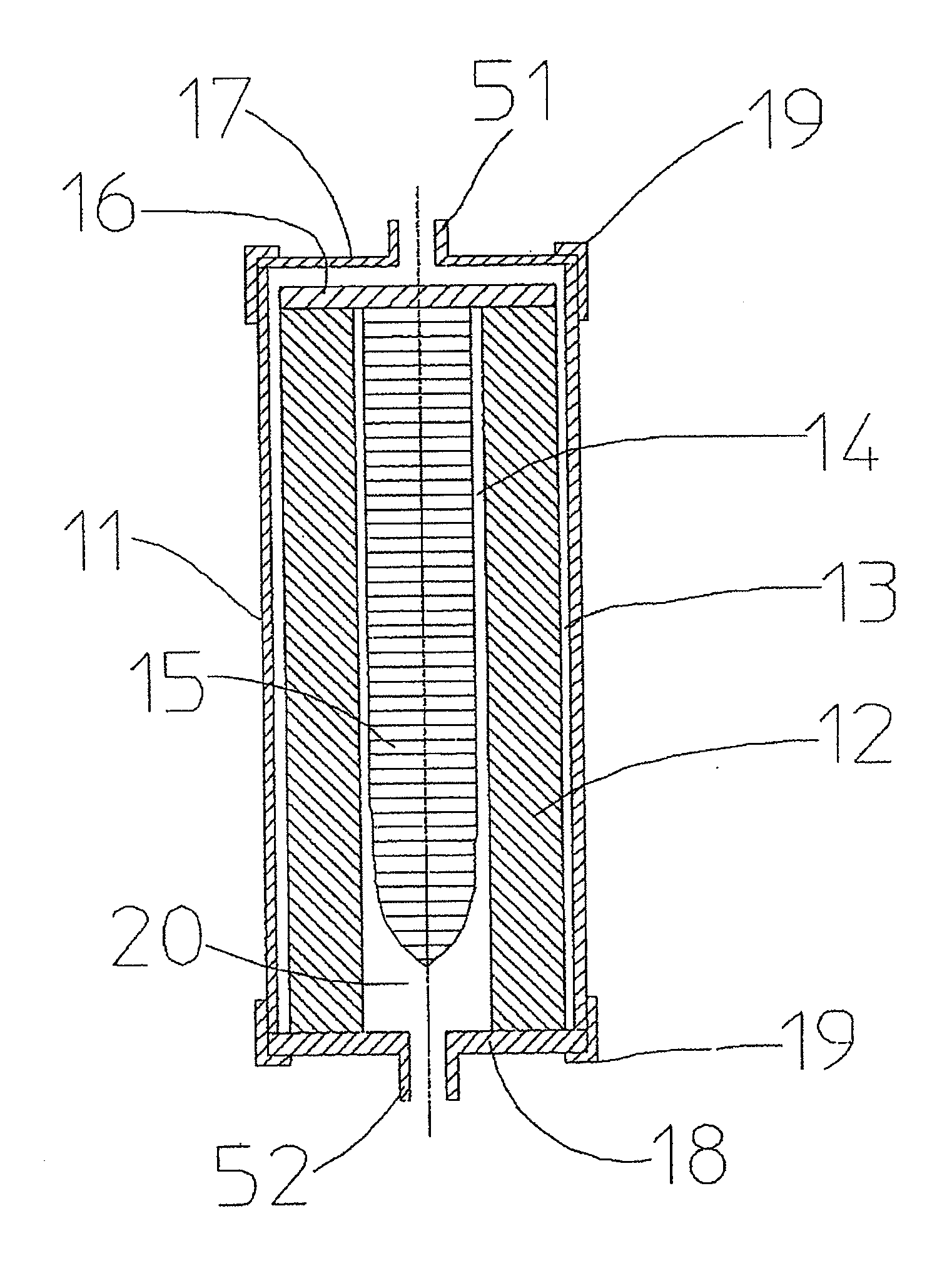
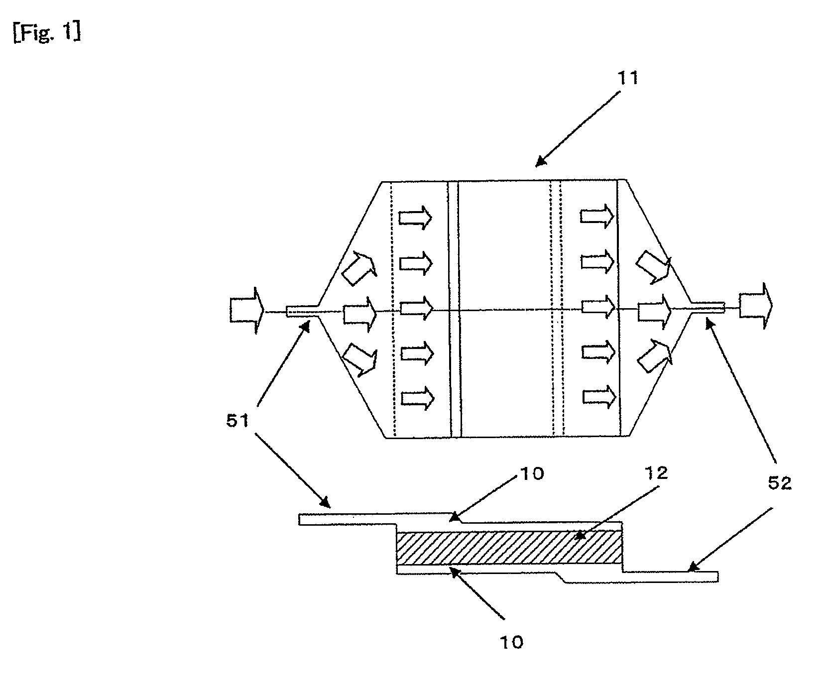
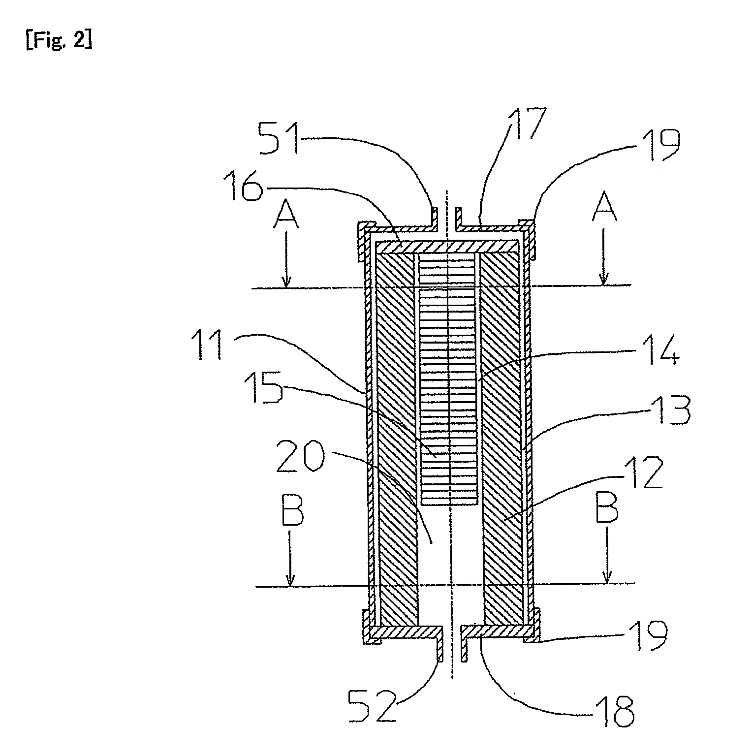
A body fluid treating filter device capable of maintaining its treating pressure within a clinically safe pressure range even if body fluid treatment is performed over a long period and having excellent property for recovering a body fluid after the body fluid treatment is completed. A body fluid treating cylindrical filter layer is stored in a cylindrical container having two body fluid flow ports. The cylindrical filter layer is disposed so that the inner space of a container can be divided into two parts by making its both end parts fluid-tight and fixing at least one of these both end parts to the inner wall surface of the container. One of the inner spaces of the container divided by the cylindrical filter layer is allowed to communicate with the first body fluid flow port and the other of the inner spaces of the container divided by the cylindrical filter layer is allowed to communicate with the second body fluid flow port. The body fluid treating cylindrical filter device is characterized in that a bar-like flow passage resistant member extending along the center axis is installed in the hollow part of the cylindrical filter layer, and a spacer layer for flowing the body fluid of 0.7 to 3.5 mm in thickness is formed between the outer peripheral surface of the cylindrical filter layer and the container and between the inner peripheral surface of the cylindrical filter layer and the flow passage resistance member.

Description

TECHNICAL FIELD[0001]The present invention relates to a body fluid-treating filter device packed with a body fluid-treating filter material for effectively removing specific components from a large amount of body fluid such as blood, plasma, and lymph fluid. The present invention further relates to a body fluid-treating filter device packed with a body fluid-treating filter material for changing the functions of components contained in a large amount of body fluid such as blood, plasma, and lymph fluid.BACKGROUND ART[0002]In recent years, there is an increasing demand for technologies for removing specific proteins, leukocytes, toxins, and the like contained in body fluids of patients to be applied to an extracorporeal circulation blood purification therapy of curing autoimmune diseases, such as systemic lupus erythematosus, chronic or malignant articular rheumatism, multiple sclerosis, chronic ulcerative colitis, and Crohn's disease, as well as other diseases such as sepsis, inflam...

Claims


Application Information

Patent Timeline
Patent Type & Authority Applications(United States)
IPC IPC(8): A61M1/16
CPCA61M1/16A61M1/3646A61M1/3606A61M1/1631
Inventor UCHI, YUKIHIKOSUKEGAWA, TAKESHI
Owner ASAHI KASEI MEDICAL CO LTD
Learn More