
Torsional Force Transmitting Apparatus

Inactive Publication Date: 2009-03-19
LIN CHONG LIANG +1
View PDF4 Cites 3 Cited by
  • Summary
  • Abstract
  • Description
  • Claims
  • Application Information

AI Technical Summary

Benefits of technology

[0006]Therefore the primary object of the present invention is to provide a torsional force transmitting apparatus that is not easily affected by temperature and generates less noise and shock.
[0008]By means of the construction set forth above, the selected amount of torsional force transmittable can be controlled through the torsional force transfer means. When the torsional force of the power output shaft is transmitted to the propeller, and the propeller hits a unknown object and results in significant increase of the torsional force and overloaded, the torsional force transfer means between the first sleeve and the second sleeve breaks and loosens, hence the first sleeve and the second sleeve rotate idly to provide protection for the propeller, engine and gear box.

Problems solved by technology

When a boat sails the propeller might hit unknown objects such as reefs.
Such an incident could generate an excessive load torsional force and result in breaking or damage of the propeller, engine and gear box.
Such an approach can save repair cost and time.
But such an approach has to rely on the press to perform replacement and repairs when damage occurs.
Used on a high horsepower engine, the temperature rises easily and the rubber becomes soft and results in slipping.
At a lower temperature the rubber becomes harder, the protection effect diminishes.
But due to the rubber is installed without being compressed in advance, and only the teeth of the gear are compressed during rotation, the compressed amount is little.
Hence the transmitting torsional force also is limited.
It is not suitable for a high power engine system.
As a result, damages of the propeller, engine and gear box could occur.
During switching a great deal of noise and shock are generated due to no buffer is provided.

Method used


Image

  • Torsional Force Transmitting Apparatus
  • Torsional Force Transmitting Apparatus
  • Torsional Force Transmitting Apparatus

Examples


Embodiment Construction

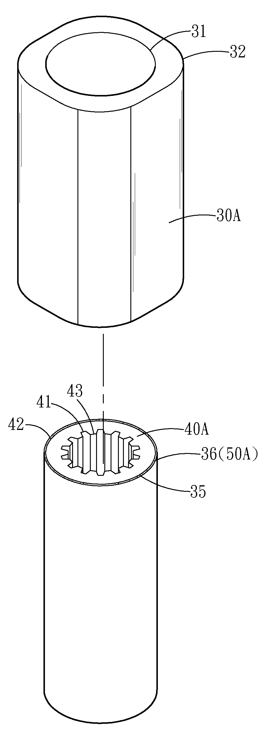
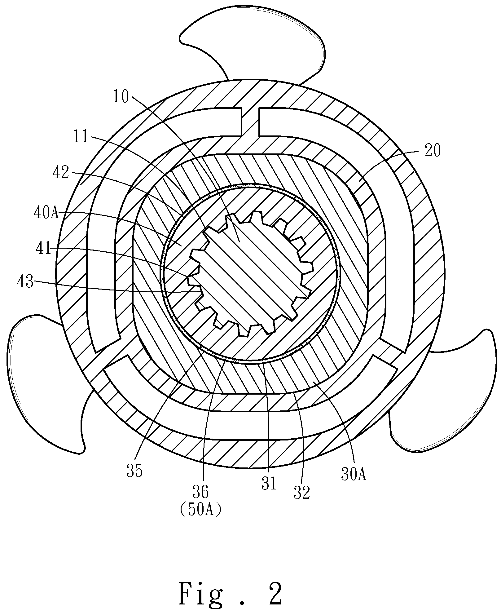
[0015]Please refer to FIGS. 1 and 2, the torsional force transmitting apparatus according to the invention aims to transmit the torsional force of a power output shaft 10 to a propeller 20. It includes a first sleeve 30A, a second sleeve 40A and a torsional force transfer means 50A. The first sleeve 30A has a first inner surface 31 and a first outer surface 32 which is non-circular. The propeller 20 also is formed in a non-circular profile such that the second outer surface 32 can be engaged with the propeller 20 in the rotating direction.

[0016]The second sleeve 40A has a second inner surface 41 and a second outer surface 42. The second inner surface 41 has annular inner teeth 43 formed thereon. The power output shaft 10 has annular outer teeth 11 mating the annular inner teeth 43 so that they can be coupled and installed together with the second inner surface 41 engaging with on the power output shaft 10 in the rotational direction. The power output shaft 10, through the mutual eng...


PUM


Abstract

The present invention aims to couple a propeller with a power output shaft to transmit the torsional force of the power output shaft to the propeller. The apparatus includes a first sleeve and a second sleeve that form a coupling surface between them to hold a torsional force transfer means. The torsional force transfer means is coupled with the first sleeve and the second sleeve to transmit only a selected amount of the torsional force. The first sleeve has a first outer surface and the second sleeve has a second inner surface that are engaged respectively with the propeller and the power output shaft in the rotating direction so that the power output shaft can transmit the torsional force to the propeller. In the event that the propeller is overloaded the torsional force transfer means between the first sleeve and the second sleeve slip to form a protection mechanism.

Description

FIELD OF THE INVENTION[0001]The present invention relates to a torsional force transmitting mechanism and particularly to a torsional force transmitting apparatus for propellers to provide overload protection.BACKGROUND OF THE INVENTION[0002]A torsional force transmitting apparatus aims to couple a propeller with a power output shaft. When a boat sails the propeller might hit unknown objects such as reefs. Such an incident could generate an excessive load torsional force and result in breaking or damage of the propeller, engine and gear box. To protect the propeller, engine and gear box, the torsional force transmitting apparatus ought to be slipping or broken. By replacing the torsional force transmitting apparatus with a new one the boat can sail again. Such an approach can save repair cost and time.[0003]However, the conventional torsional force transmitting apparatus used on a propeller is formed by squeezing a round rubber into a round inner hole of the propeller through a pres...

Claims


Application Information

Patent Timeline
IPC IPC(8): B63H5/07
CPCB63H23/34
Inventor LIN, CHONG-LIANGLIAO, SHU-XIA
Owner LIN CHONG LIANG
Learn More