Turbine engine with differential gear driven fan and compressor

a technology of differential gears and turbine engines, applied in the direction of machines/engines, mechanical equipment, gearing, etc., can solve the problems of not being able to achieve the ideal power/speed spli

Active Publication Date: 2009-03-19
RTX CORP
View PDF75 Cites 65 Cited by
  • Summary
  • Abstract
  • Description
  • Claims
  • Application Information

AI Technical Summary

Benefits of technology

[0009]As an additional, optional feature, an amplifying gear system provides a speed increase from the turbine to the differential gear. In the example shown., the amplifying gear system is also an epicycle gear system, in particular, a star gear system. The turbine is coupled to a ring gear, which drives star gears mounted on a carrier mounted to static structure in the turbine engine. The star gears also drive a sun gear, which is coupled to the sun gear of the differential gear system.
[0010]In another optional feature, a tower shaft engages a high spool of the turbine aft of the turbine. The tower shaft provides rotational input to the turbine in order to start the turbine engine.

Problems solved by technology

However this may not be the ideal power / speed split during all conditions.

Method used


Image

  • Turbine engine with differential gear driven fan and compressor
  • Turbine engine with differential gear driven fan and compressor
  • Turbine engine with differential gear driven fan and compressor

Examples


Embodiment Construction

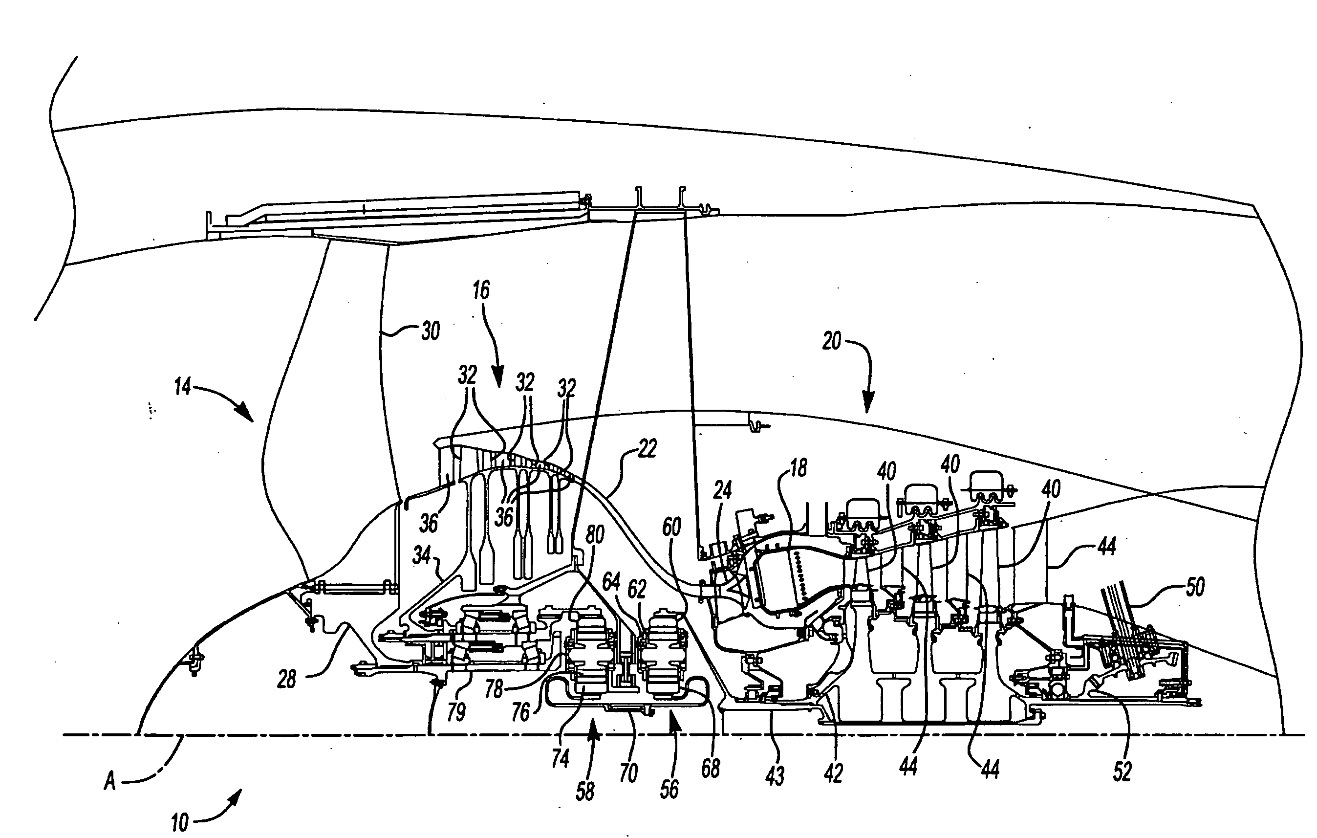
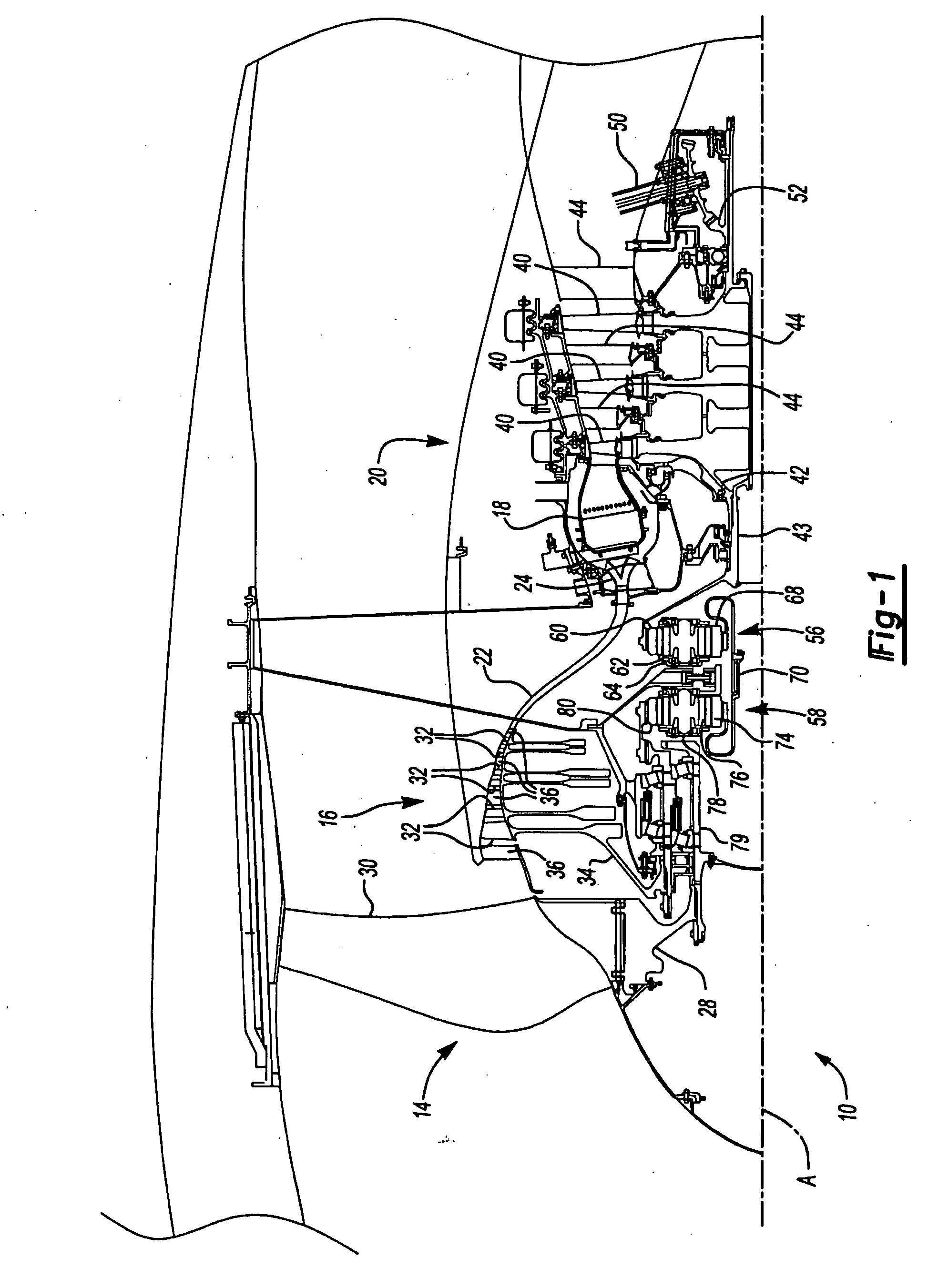
[0014]A gas turbine engine 10 circumferentially disposed about an engine centerline A is shown in FIG. 1. The engine 10 generally includes a fan 14, a low pressure compressor 16, a combustor 18 and a turbine 20. Generally, air compressed in the low pressure compressor 16 is mixed with fuel which is burned in the combustor 18 and expanded in turbine 20. The air flow path through the low pressure compressor 16, through the combustor 18 and the turbine 20 may be referred to as the core air flow path 22.

[0015]The fan 14 includes a fan hub 28 and a plurality of fan blades 30. The plurality of fan blades 30 extends radially outwardly from the fan hub 28 across the bypass air flow path and the core air flow path.

[0016]The low pressure compressor 16 includes a plurality of blades 32 extending radially from a compressor rotor 34. A plurality of static vanes 36 extend between some adjacent pairs of rows of blades 32. The core air flow path 22 turns radially inwardly between the low pressure c...


PUM


Abstract

A gas turbine engine (10) provides a differential gear system (58) coupling the turbine (20) to the bypass fan (14) and the compressor (16). In this manner, the power/speed split between the bypass fan and the compressor can be optimized under all conditions. In the example shown, the turbine drives a sun gear (74), which drives a planet carrier (78) and a ring gear (80) in a differential manner. One of the planet carrier and the ring gear is coupled to the bypass fan, while the other is coupled to the compressor.

Description

[0001]This invention was conceived in performance of NASA contract NAS3-98005. The government may have rights in this invention.BACKGROUND OF THE INVENTION[0002]This invention relates to turbine engines and more particularly to a turbine engine using a differential gear to drive the fan and compressor.[0003]A gas turbine engine, such as a turbo fan engine for an aircraft, includes a fan section, a compression section, a combustion section and a turbine section. An axis of the engine is centrally disposed within the engine and extends longitudinally through the sections. The core air flow path extends axially through the sections of the engine. A bypass air flow path extends parallel to and radially outward of the core air flow path.[0004]The fan section includes a plurality of radially extending fan blades. The fan blades extend through the bypass flow path and interact with the air and transfer energy between the blades and air. A fan case circumscribes the fan in close proximity t...

Claims


Application Information

Patent Timeline
Patent Type & Authority Applications(United States)
IPC IPC(8): F02C3/113F02C7/36
CPCF02C3/113F02C7/36F05D2260/40311F04D25/04F02K3/06
Inventor SUCIU, GABRIEL L.PAGLUICA, GINO J.DUONG, LOC QUANGPORTLOCK, LAWRENCE E.
Owner RTX CORP
Why Eureka
Try Eureka