
Light Guide Plate and Direct-Type Surface Light Source Device

a light guide plate and surface light source technology, which is applied in the direction of lighting and heating apparatus, instruments, optical elements, etc., can solve the problem of narrow application of light guide plates in some degree, and achieve the effect of improving assembly convenience and high light utilization efficiency

Inactive Publication Date: 2009-03-19
NANO PRECISION
View PDF5 Cites 13 Cited by
  • Summary
  • Abstract
  • Description
  • Claims
  • Application Information

AI Technical Summary

Benefits of technology

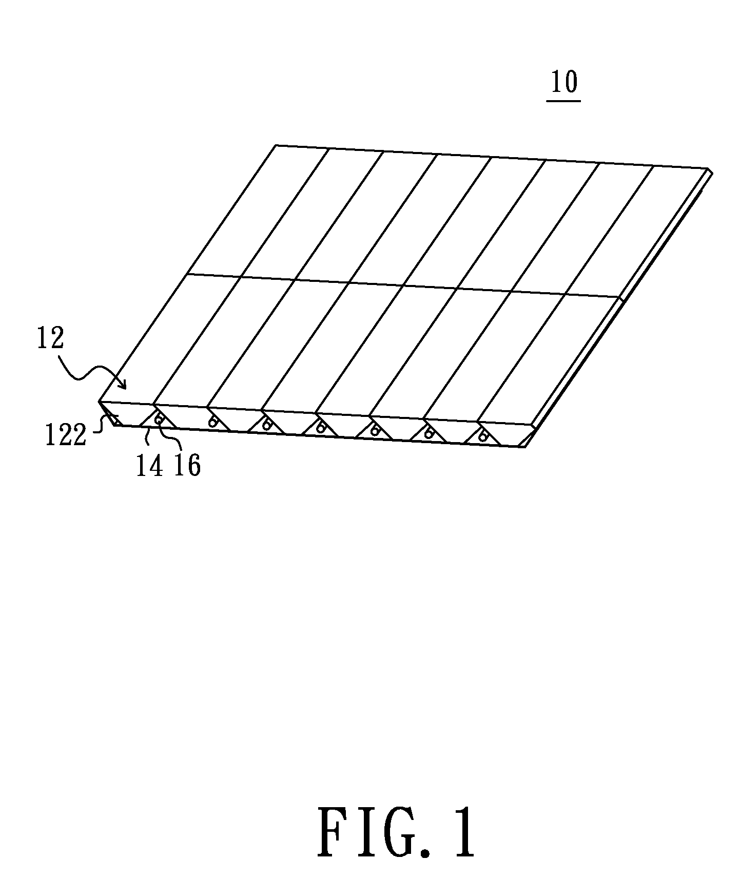
[0008]Since the light guide plate is formed by a plurality of light guide units joined with one another, the light guide plate can be configured with any size by changing the amount of the light guide units and thus the direct-type surface light source device using the same can match any sized liquid crystal display panel. Furthermore, the structural configuration of the first and second side surfaces between the light exit surface and the bottom surface for each of the light guide units allows light beams emitted from the light sources to be effectively directed / guided toward the substantially flat surface for output, and thereby high light utilization efficiency may be achieved. In addition, the bottom surfaces of the light guide units are surface shaped structure, which can improve the assembly convenience of the light guide plate when being applied to the direct-type surface light source device.

Problems solved by technology

In other words, single design of the light guide plate could not match the LCD panels with different sizes and thus the applicability of the light guide plate is narrow in some degree.

Method used


Image

  • Light Guide Plate and Direct-Type Surface Light Source Device
  • Light Guide Plate and Direct-Type Surface Light Source Device
  • Light Guide Plate and Direct-Type Surface Light Source Device

Examples


Embodiment Construction

[0021]In the following detailed description of the preferred embodiments, reference is made to the accompanying drawings which form a part hereof, and in which are shown by way of illustration specific embodiments in which the invention may be practiced. In this regard, directional terminology, such as “top,”“bottom,”“front,”“back,” etc., is used with reference to the orientation of the Figure(s) being described. The components of the present invention can be positioned in a number of different orientations. As such, the directional terminology is used for purposes of illustration and is in no way limiting. On the other hand, the drawings are only schematic and the sizes of components may be exaggerated for clarity. It is to be understood that other embodiments may be utilized and structural changes may be made without departing from the scope of the present invention. Also, it is to be understood that the phraseology and terminology used herein are for the purpose of description an...


PUM


Abstract

A light guide plate includes a plurality of light guide units each including a light exit surface, a bottom surface, a first side surface and a second side surface. The first and the second side surfaces respectively include a first oblique surface and a second oblique surface. The first and the second oblique surfaces are opposite to each other and both adjoining the bottom surface. The first side surface of one of the each two adjacent light guide units is joined with the second side surface of the other one and thereby the light exit surfaces of the light guide units cooperatively form a substantially flat surface. The light guide units define a plurality of receiving cavities spaced apart from one another by the first and the second oblique surfaces thereof. In addition, a direct-type surface light source device using the light guide plate also is provided.

Description

BACKGROUND[0001]1. Technical Field[0002]The present invention generally relates to a light guide plate and a direct-type surface light source device and, particularly, to a light guide plate in any size with a high light utilization efficiency and a direct-type surface light source device using the same.[0003]2. Description of the Related Art[0004]Liquid crystal displays (LCDs) are primarily employed in various information, communication and consume products, such as personal computers, liquid crystal televisions, mobile phones, videophones, personal digital assistants and so on. Because a LCD panel is non-emissive, a backlight module is necessarily required for providing an uniform and high brightness surface light source to achieve a good visual effect. A direct-type surface light source device is one type of backlight module and generally is applied to large-sized liquid crystal displays.[0005]The direct-type surface light source device generally includes a light guide plate and ...

Claims


Application Information

Patent Timeline
Patent Type & Authority Applications(United States)
IPC IPC(8): F21S4/00
CPCF21V7/0091G02B6/0045G02B6/0021F21Y2103/00
Inventor CHEN, CHIEN-HSIANGLIU, MING-DAH
Owner NANO PRECISION
Learn More