
Motion capture device and associated method

Inactive Publication Date: 2009-03-12
COMMISSARIAT A LENERGIE ATOMIQUE ET AUX ENERGIES ALTERNATIVES
View PDF15 Cites 4 Cited by
  • Summary
  • Abstract
  • Description
  • Claims
  • Application Information

AI Technical Summary

Benefits of technology

[0053]The system of local measurements may for example be a device of the GPS type (GPS standing for “Global Positioning System”) associated with a differentiating circuit. The GPS device makes it possible to know at any time the position of the element that carries it and a differentiating circuit, by differentiating the position data twice, determines the absolute acceleration in the geographical reference frame.
[0054]The system of local measurements can also be implemented by means of a radio location device associated with a differentiating circuit. Radio location devices require the use of beacons (ULB radar (U

Problems solved by technology

In all cases, these systems have a short range (in keeping with the range of the physical source) and a fairly lengthy installation and calibration phase.
Their cost is also very high.
Despite this, the problems of optical occlusion are numerous, which makes the minimum number of cameras used high.
These two technologies suffer from the same limitation in space as camera-based technology.
The capture of rapid movements does nevertheless remain a problem if the accelerations remain, since the resetting no longer occurs.
In addition, gyrometers are sensors still difficult to use, fairly expensive and also having certain sensitivity to accelerations.
Without additional information, the device therefore does not allow the measurement of the orientation angles when the moving object is accelerated or at least when the acceleration of the moving object cannot be ignored.
This represents a drawback.

Method used


Image

  • Motion capture device and associated method
  • Motion capture device and associated method
  • Motion capture device and associated method

Examples


Embodiment Construction

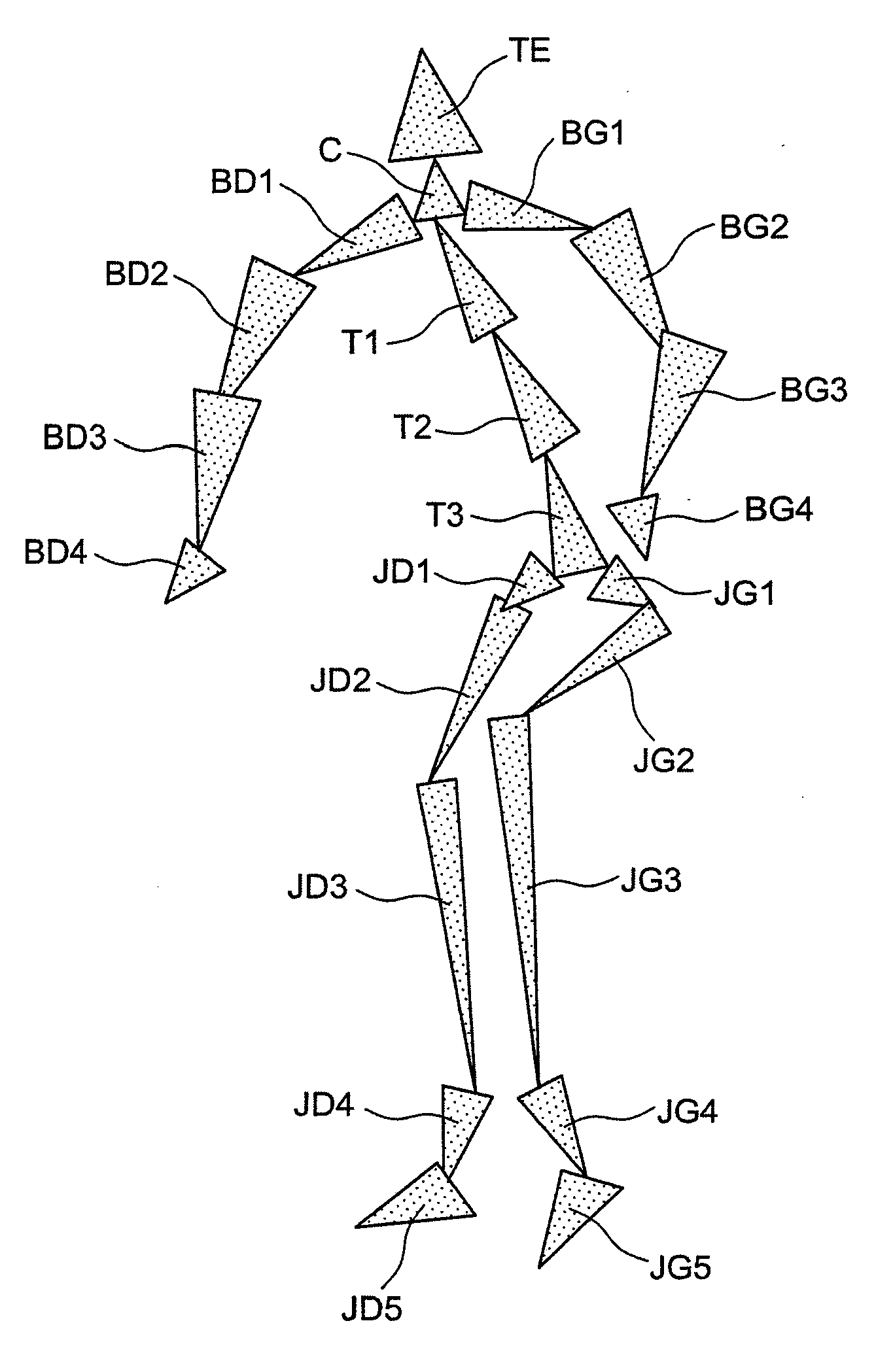
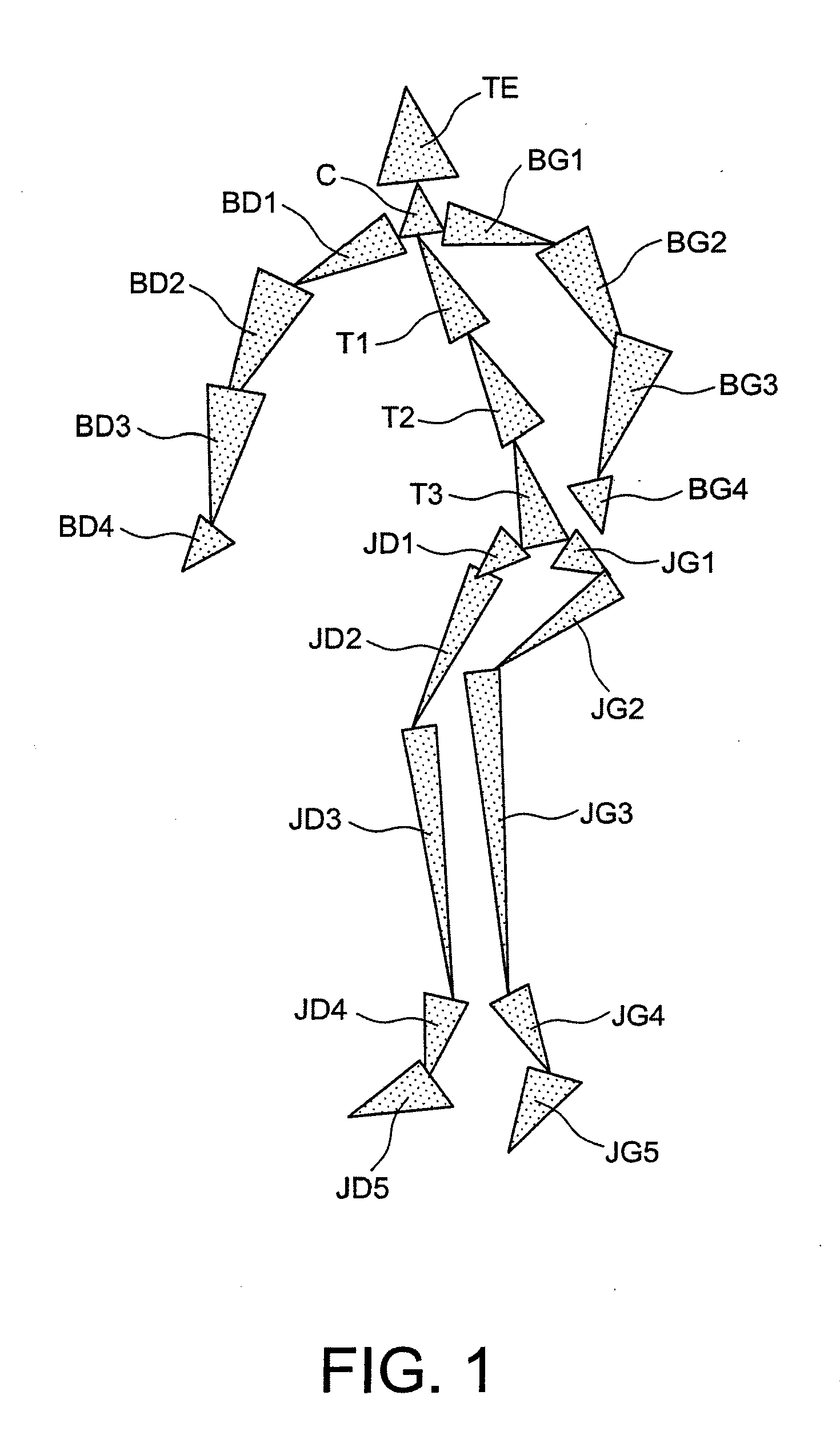
[0074]FIG. 1 depicts an example of an articulated structure to which the motion capture device of the invention relates.

[0075]The structure, for example a human body or a humanoid robot, is broken down into a set of segments which are so many solid elements articulated with respect to one another. All the segments are thus broken down into a head segment TE, a neck segment C, a set of trunk segments T1, T2, T3, a set of left arm segments BG1, BG2, BG3, GB4, a set of right arm segments BD1, BD2, BD3, BD4, a set of left leg segments JG1, JG2, JG3, JG4, JG5 and a set of right leg segments JD1, JD2, JD3, JD4, JD5.

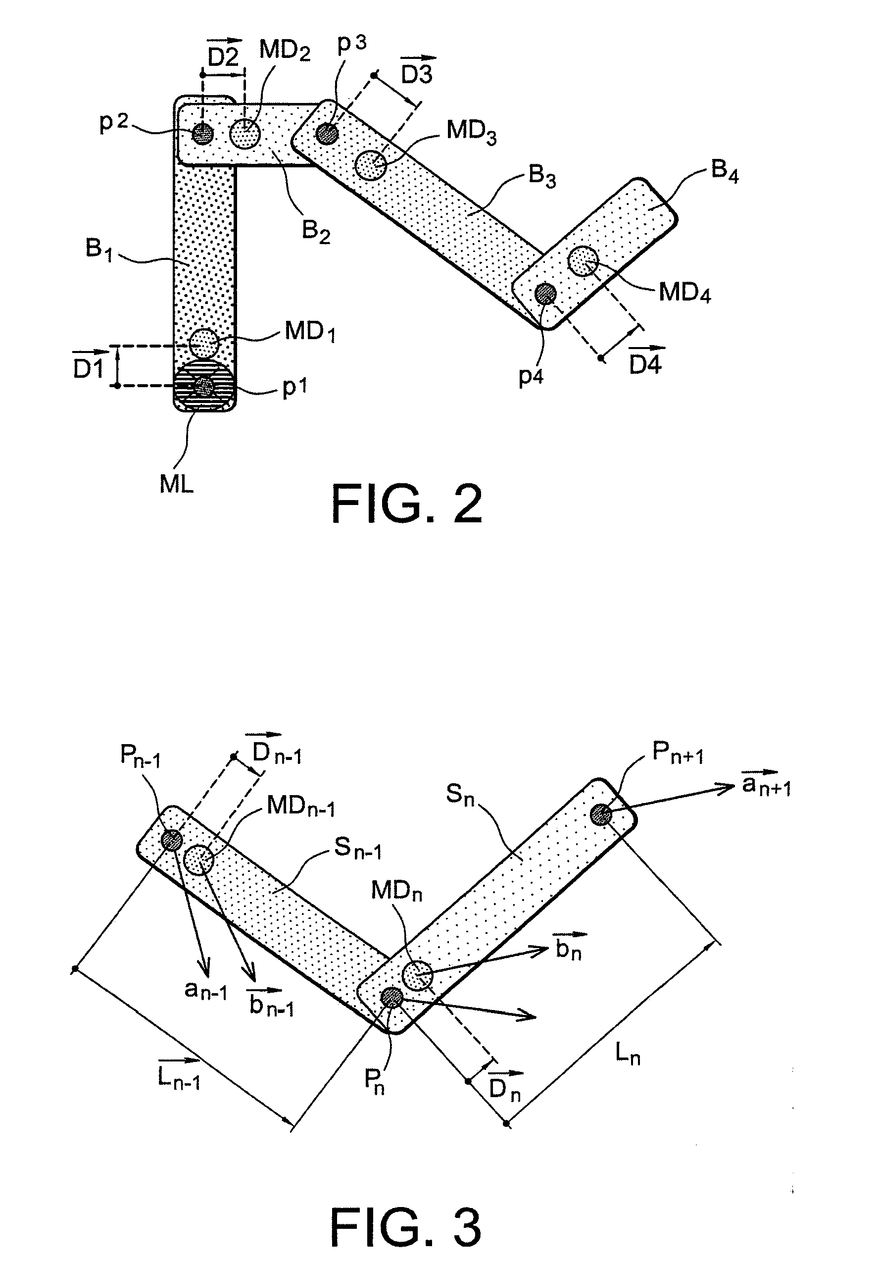
[0076]FIG. 2 depicts an articulated structure provided with a motion capture device according to the invention. The structure is for example a robot arm consisting of four articulated segments B1, B2, B3, B4 ranging from the shoulder to the hand.

[0077]The segment B1 is provided with a system of local measurements ML and an elementary orientation-measurements device MD1. The ele...


PUM


Abstract

The invention concerns a device for capturing the motion of a structure consisting of N articulated segments, characterised in that it comprises:first means (ML) that deliver at least one item of information able to restore an absolute acceleration vector {right arrow over (a)}1 of a point on the segment of rank 1 in a reference frame forming a reference, at successive times tk, k being an integer number greater than or equal to 1, andsecond measuring means (MD1, MDn) distributed over the various segments and which deliver, for each segment of rank 1 to N, at each time tk, a measurement (M1, Mn) representing an orientation vector ({right arrow over (Θ)}1, {right arrow over (Θ)}n) of the segment in the reference frame.Application to biomechanical analysis, telemanipulation, animation of characters, etc.

Description

TECHNICAL FIELD AND PRIOR ART[0001]The invention concerns a motion capture device and the associated motion capture method. The invention also concerns a motion reproduction device and the associated motion reproduction method.[0002]A device for capturing the motion of a structure is a device that measures quantities able to describe, by processing, the motion of the structure. The structure may for example be a person or robot, moving about or not.[0003]The capture of human motion is a technique very much used in many applications: biomechanical analysis, telemanipulation, animation of a character, ergonomics, etc.[0004]A first category of motion capture devices consists of devices that comprise two distinct parts: a first part is placed on the moving object and a second part is fixed with respect to the movement of the object. In this first category, there are mainly optical systems, electromagnetic systems and ultrasound systems. These devices are effective in terms of precision....

Claims


Application Information

Patent Timeline
IPC IPC(8): G06K9/00
CPCA61B5/103A61B5/11A61B5/4528A61B2562/0219G06F3/011A61B2562/0233A61B2562/04G01C21/16A61B2562/0223
Inventor CARITU, YANISDAVID, DOMINIQUEGODIN, CHRISTELLE
Owner COMMISSARIAT A LENERGIE ATOMIQUE ET AUX ENERGIES ALTERNATIVES
Learn More