
Interpolation Method and a Related Device for Channel Estimation in Communication Systems

a communication system and channel estimation technology, applied in the field of interpolators, can solve the problems of unsuitable channel estimation and unsatisfactory interpolation methods in the art, and achieve the effect of cost-effectiveness and flexible variation

Inactive Publication Date: 2009-03-12
TELECOM ITALIA SPA
View PDF8 Cites 11 Cited by
  • Summary
  • Abstract
  • Description
  • Claims
  • Application Information

AI Technical Summary

Benefits of technology

[0030]The Applicant has tackled the problem of providing an interpolation method which can be cost-effectively implemented in hardware and which allows to vary flexibly the number of interpolated points without requiring any modification in the device implementing such a method.
[0033]It is a second object of the present invention to provide a very simple and fast interpolation circuit that can be implemented with conventional logic circuitry, such as the basic logic elements that are available in programmable logic devices (e.g. FPGA).
[0035]Moreover, the method according to the invention is particularly suitable for applications where it is required an interpolation between two values with a very short computation time.
[0036]It is a third object of the present invention to provide an interpolation method that can be cost-effectively implemented in hardware.

Problems solved by technology

The Applicant has observed that the interpolation methods proposed in the art are not completely satisfactory.
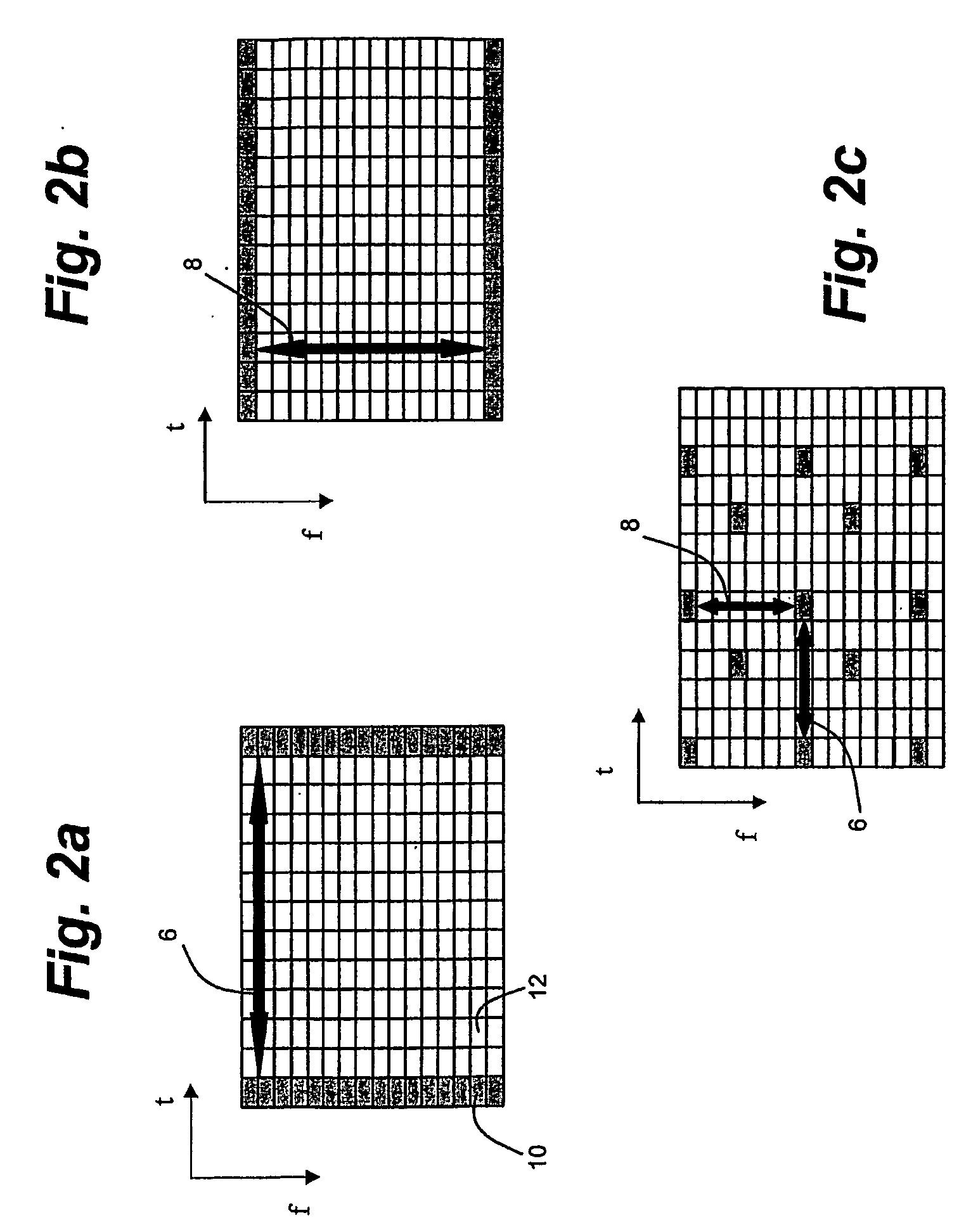
The interpolation methods described in U.S. Pat. No. 5,886,911 and in U.S. Patent Application No. 2002 / 0152248 are therefore not suitable for channel estimation in communication systems, since in such an estimation the number of interpolated points should be dynamically varied in accordance with the selected pilot pattern.

Method used


Image

  • Interpolation Method and a Related Device for Channel Estimation in Communication Systems
  • Interpolation Method and a Related Device for Channel Estimation in Communication Systems
  • Interpolation Method and a Related Device for Channel Estimation in Communication Systems

Examples


example 1

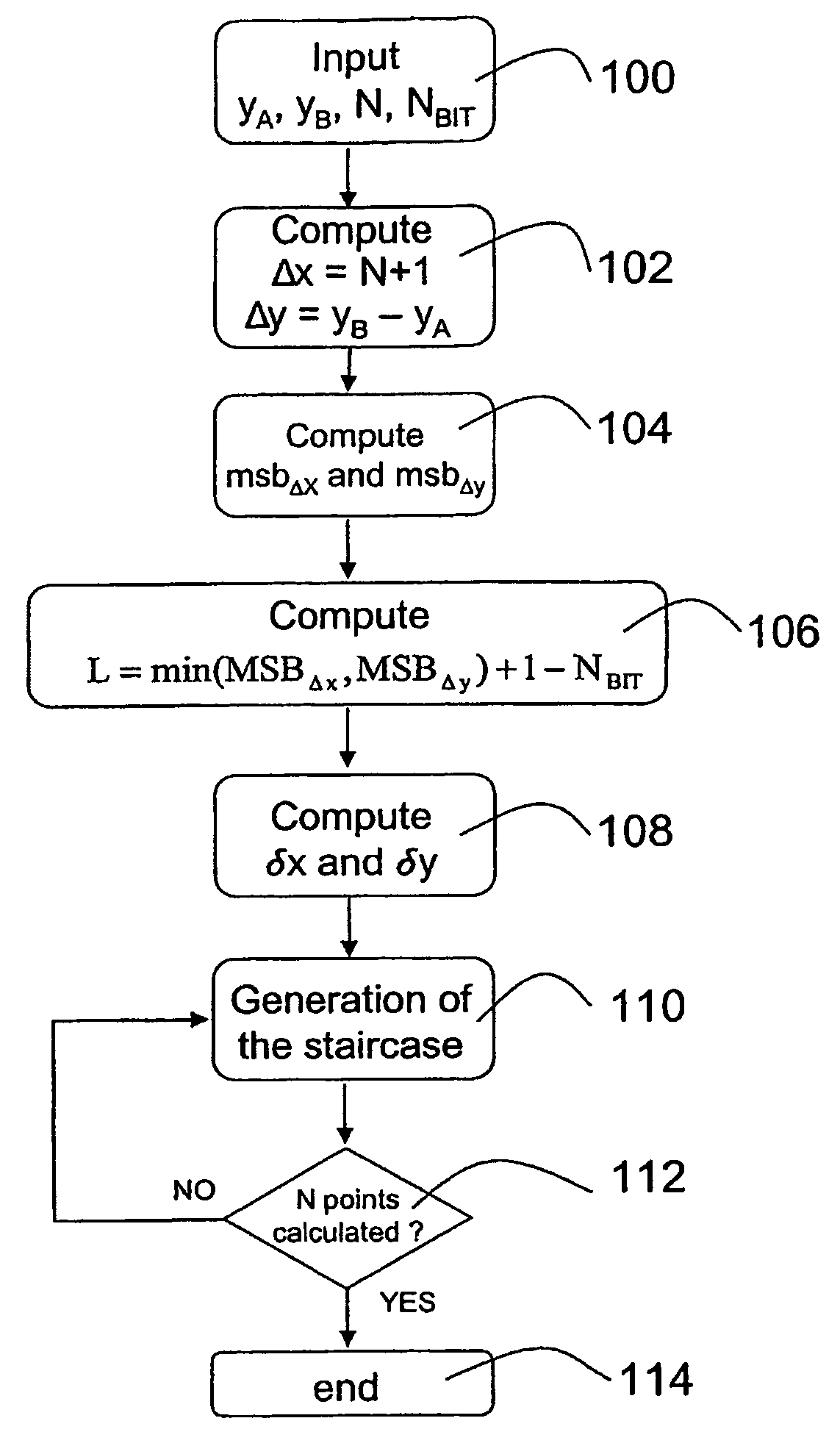
[0089]Input Data Of The Interpolation Algorithm[0090]Number of interpolated values: N=11[0091]First known point: A=(xA,yA)=(0, 10)[0092]Second known point: B=(xB,yB)=(xAN+1,yB)=(0+11+1,18)=(12, 18)[0093]Minimum resolution of δx and δy in bits: NBIT=2

[0094]First Step: Calculation of the Interval Lengths Δx and Δy

Δx=xB−xA=12−0=12 =11002

Δy=yB−yA=18−10=8=10002

[0095]Second Step: Calculation of L[0096]MSBΔx=3[0097]MSBΔy=3

L=min(MSBΔx,MSBΔy)+1−NBIT=min(3,3)+1−2=2

[0098]Third Step: Calculation of δx and δy

δx=Δx>>L=11002>>2=112=3

δy=Δy>>L=10002>>2=102=2

[0099]Fourth Step: Generation of the Interpolation Function. The ordinate of the interpolated points is kept constant for a group of δx consecutive points (hold step) and then varied of δy (variation step). The process starts from the known point A and is repeated iteratively until N interpolated points between A and B are generated. In this case all the steps of the interpolation function have the same length and each step is composed of δx=3...

example 2

[0100]Input Data of the Interpolation Algorithm[0101]Number of interpolated values: N=10[0102]First known point: A=(xA,yA)=(0, 5)[0103]Second known point: B=(xB,yB)=(xA+N+1,yB)=(0+10+1,28)=(11, 28)[0104]Minimum resolution of δx and δy in bits: NBIT=2

[0105]First step: Calculation of the Interval Lengths Δx and Δy

Δx=xB−xA=11−0=11=10112

Δy=yB−yA=28−5=23=101112

[0106]Second step: Calculation of L[0107]MSBΔx=3[0108]MSBΔy=4

L=min(MSBΔx,MSBΔy)+1−NBIT=min(3,4)+1−2=2

[0109]Third step: Calculation of δx and δy

δx=Δx>>L=10112>>2=102=2

δy=Δy>>L=101112>>2=1012=5

[0110]Fourth Step: Generation of the Interpolation Function. The ordinate of the interpolated points is kept constant for a group of δx consecutive points (hold step) and then varied of δy (variational step). The process starts from the known point A and is repeated iteratively until N interpolated points between A and B are generated. In this example the last step of the interpolation function has a different length because it is composed o...


PUM


Abstract

A method for interpolating between a first and a second point includes the steps of calculating a first distance between a first and a second independent value and a second distance between a first and a second dependent value, right shifting the first and the second distances by a predetermined number of bits for obtaining respectively a hold step and a variations step and generating a number of interpolated points, having independent values between the first and the second independent values and corresponding dependent values obtained by alternating hold and variations phases, wherein the hold phase consists of generating a number of points corresponding to the hold step having the same dependent value, and wherein the variations phase consists of varying the dependent value by the variations step until the number of interpolated points has been calculated. The method is particularly suitable for channel estimation in communication systems.

Description

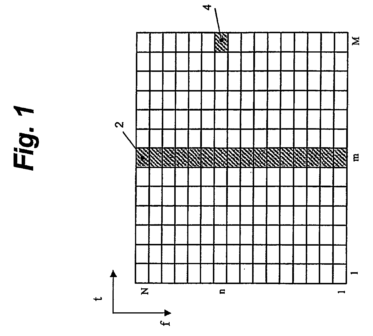
TECHNICAL FIELD[0001]The present invention relates to an interpolator. More particularly, the present invention relates to an interpolation method and to the related device that is cost-effectively implemented in hardware using digital circuits of minimal complexity.[0002]The method according to the invention is particularly suitable for the interpolation of fixed point signals, namely sampled signals whose values are represented using finite precision arithmetic.BACKGROUND ART[0003]Interpolation techniques are used in a number of technical fields. For example, interpolation techniques are used in digital receivers for channel estimation purposes. In fact, in many wireless or wired transmission systems the channel estimation is performed by means of training sequences, known to the receiver, that are multiplexed with the user data.[0004]Training sequences are typically transmitted only in a part of the transmission frame. The remaining part of the frame is used for the transmission ...

Claims


Application Information

Patent Timeline
Patent Type & Authority Applications(United States)
IPC IPC(8): H04L25/02
CPCH04L25/0232G06F17/17
Inventor MELIS, BRUNORUSCITTO, ALFREDOCAMPANALE, ROSALBA
Owner TELECOM ITALIA SPA
Learn More